| Search results - "Vehicle" |
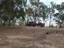
02 On banks of Darling River, Back of Bourke158 views"Back of Bourke" is the typical definition of the start of the Australian Outback. This was after crossing the Darling River "back of Bourke" on 8 Jan 08. We were the first vehicle to start driving after floods had closed (first time in 8 yrs there was any water in the river).
|
|
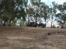
02 Last Photo before the little wheel problem saga222 viewsThis is my D3 with trailer on the banks of the Darling River, literally "back of Bourke" (the regional definition of the start of the Australian Outback). We were the first vehicle in a week to try and drive this route from Bourke to Wilcannia on the account of floods (first water in 7 years). Little did we know that 3 hours later there\'d be a bit of a wheel and tyre problem appearing...
|
|

Thread upload16 viewsImage uploaded in thread 137890
|
|

Thread upload28 viewsImage uploaded in new thread
|
|

14 views
|
|

28 viewsSuspension fault codes
|
|

Air Suspension Air Filter53 views
|
|
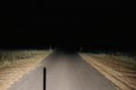
Standard Vehicle Low Beam Lights Only (Bi-Xeons)32 views
|
|

1-34 FormulaShell Multi-Vehicle A T F84 views
|
|
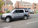
Both Team Poteen vehicles130 views
|
|
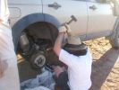
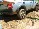
11 Lesson in removing a jammed brake assembly in the Outback378 viewsSpent the next 4 hours doing this to my D3. Gave the photos to Land Rover dealer and they did not think this constituted abuse of the vehicle. I thought that was charitable, but if we hadn\'t done this, the tow back to civilisation would have been even longer.
|
|
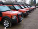
\'09 Event Vehicles154 views
|
|
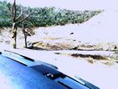
Recovery vehicle bogged for second time62 views
|
|
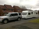
Long Vehicle66 views
|
|
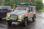
Northumberland National Park Mountain Rescue Team Vehicle14 views
|
|
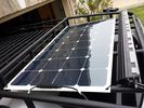
solar roof install444 viewsMore or less wrapped up my solar installation today. I added a Grape Solar Flex 100W panel, it's adequate to keep the vehicle topped off with the Fridge running, and Ham, but it could lose some ground if transmitting depending on how much, 2 would be awesome. One is enough, but barely. I am quite impressed with the Grape Solar flex panel version 2.0.
https://www.facebook.com/DifferentialPartsUS
|
|

\'09 Event Vehicles132 views
|
|
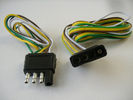
4 pin NAS flat connector from NAS small trailer382 viewsThe connector with the three exposed pins is the end that would commonly be located at the trailer hitch end, (front), of a small NAS lightweight trailer that has no electric brakes. This plug would connect into the flat 4 pin connector at the rear of the 3.
Note the order of the pin functions and wire colours: White is ground; the next pin is for tail/marker lights using the Brown wire; the Yellow conductor is for the left turn signal, and the far pin uses the Green conductor for the right turn signal.
There is no separate brake light conductor as NAS spec vehicles most often combine the brake and signal light functions to the same bulb filament rather separate filaments in different bulbs. The LR factory harness resolves that design difference.
Fortunately, the Land Rover NAS assembly pin order for the 4 pin flat plug maintains the above described conventions.
|
|

Alternator and Regulator Wiring Diagrams, TDV6 and petrol V8 and V61989 viewsThis is a three page pdf that shows the alternator and regulator wiring for the petrol V6, petrol V8 and TDV6. The pdf can be either printed or by right clicking on the displayed pdf, rotated as required for viewing.
Of interest is that the regulator gets its instructions primarily from the Engine Control Module (ECM) and only secondarily from the vehicles electrical buss. The conductor from the battery thru the 5 amp fuse F20E is to provide initial power to excite the alternator at startup and then secondarily, to instruct it if the PWM signals were not available. Primary instructions to and from the ECM are thru the two other conductors via a digital like Pulse Width Modulated (PWM) signal.
If F20E, the 5 amp engine compartment fuse box fuse is blown, the red alternator light on the dash will be illuminated. This means that the alternator could be OK, but if the F20E fuse is blown, no electricity will be generated. Hence check the F20E fuse if you get a red ALT light or some indication of the alternator not working.
Regarding operation of the red ALT light on the dash, it is not the regulator within the alternator that tells the red light to illuminate, or not, but instead the ECM. This is the reason the red light does not function in the same manner as with older vehicles. With the 3, sometimes you have illumination and sometimes not depending upon what the ECM is thinking. What this means is that you can have an alternator that is failing but the red light does not illuminate as the ECM is compensating for reduced alternator output - maybe by draining the battery and or cutting back on vehicle electrical loads such as shutting off or cycling the radio amplifier or heated seats.
|
|

\'09 Event Vehicles121 views
|
|

My Weekend Vehicle39 views
|
|
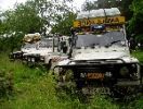
Less refined vehicles...59 views
|
|

View across the plain113 viewsThis was a shot across the plain taken with my KM Z5 at maximum 12x optical resolution - these vehicles were a long long long way away!
|
|

Land Rover Aerial Fin images for both Glass and Metal Roof Disco3 / LR3863 viewsAs well as the two different fins, this pdf also shows the plastic blanking plate for glass roof vehicles where no fin is installed.
The glass roof fin is secured by two security screws from the top into a plastic frangible glue on gasket. The hope is that when struck, the fin will shear off and not crack the glass roof. Re the metal roof design, the fin is secured from underneath via two nuts.
The pdf also shows the various electrical bits related to the antennas. In the UK, the fin would house not only a cell phone antenna but the TV and satellite radio antenna electronics as well; in the States, the Sirius sat radio antenna and a G type cell phone antenna if the phone kit was installed would reside within the fin. The SAT NAV GPS antenna is located within the High Mount Brake Light plastic mounted to the upper rear hatch.
|
|

ALMA CUSTOM VEHICLE FOR MOVING MASTS OVER DESERT92 views
|
|

Alternator female plug looking down into top373 viewsThis shows the plug connected to the alternator wiring harness looking down into the top of the plug.
The cavity marked 1 is the AS or BATT SENSE and the wire colour most likely has Brown/Green on it.
The cavity marked 2 is the RC or ALT CON and the wire colour most likely has Red/White on it.
The cavity marked 3 is the L1 or ALT MON and the wire colour likely has Green/White on it.
I say "most likely" as the wire colours are not always the same on all vehicles.
Also the terminal 1 conductor destination is more likely C0570-175 rather than per the jpg.
The #3 pin is located closest to the big B+ terminal.
|
|

Amp Drawing53 viewsThis is how many amps my vehicle was using when the ign in possision II. Lights where off, radio off,hvac off Crazy?
|
|
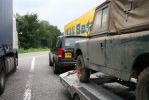
208 viewsin its usual state with a 5.6 m trailer weighing anything up to 3.5 tons. it is the best tow vehicle i have ever owned and eve better than my 130 land rover
|
|
10 views
|
|

10 views
|
|
7 views
|
|
9 views
|
|
9 views
|
|
Thread upload5 viewsImage uploaded in thread 116621
|
|
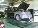
new vehicle electronic test109 viewsmy new vehicle goes through the final pre slae tests
|
|
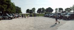
The Disco3 Squad, Saturday Morning216 viewsA stitch together of two photos showing all sixteen vehicles read for the off out and about in the Peak District on 1st July
|
|
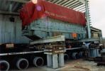
Grand Cayman97 viewsA 120tonnes Diesel Engine being skidded from road transport vehicle to final position in Grand Cayman,we were responsible from Stockport up to final job site,including al shipping and transportation.
|
|
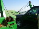
All at sea in an LR3105 viewsThe ferry from the mainland to Mazira Island was packed to the gunnels with vehicles. My LR3 was last on and they left the bow doors partially open for 14 lonnnnng sea miles across the Arabian Gulf!
|
|
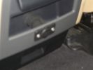
Auxiliary power sockets - TracTronics, Australia382 viewsA complete kit including two outlets, wiring etc connected to auxiliary Optima Blue top battery using their very effective SC40 split charge relay. One outlet between rear and front seats, and 2nd alongside loadspace 12v outlet, enables fridge to run when engine is not running, without affecting start capacity or vehicle functions.
|
|
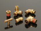
Detroit Fluid DOT air line fittings718 viewsThe picture shows the internal ferrule that is characteristic of the DOT / TUV accepted fittings for highway vehicles. Most often these fittings are metal however the Land Rover John Guest 6mm straight connector is all plastic and has the internal ferrule.
|
|
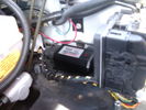
CounterAct Power Supply mounted 246 viewsPicture is blurred, however power supply is 3M two sided tape to the flat black plastic of the second battery compartment just under the antilock brake pipes to the fender side of the brake fluid reservoir. The white wire to the left rear coupler pad runs thru the firewall hole near the steering column. The blue wire to the right front coupler runs across and above the engine following the other wiring looms that cross the vehicle.
|
|
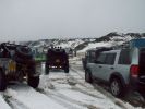
Lonely Disco3 amongst the tricked up 90s and Disco 1s at Cowm90 views
|
|

Approved Vehicle Programme Multi-Point Inspection Check List Appendix26 viewsApproved Vehicle Programme Multi-Point Inspection Check List Appendix
|
|
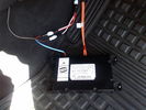
D4 Bluetooth AH42 10F845 AA module connected to 12VDC and MOST1210 viewsThis jpg shows the MOST bus connected to the AH42 10F845 AA module used in the D4 as well as +12VDC power from F58P connected. The power is split with a Y harness as the IHU (radio) for some reason required +12VDC power to the C2115-10 "mute" pin to keep the radio/CD audio from muting all the time.
With power on the pin, the radio audio does mute as it should when the cell phone rings and the hands free connects. The brown conductor feeds to C2115-10 and the blue to the module.
The module tucks up and hides behind the grey plastic section covering the forward portion of the passenger side tranny hump for left hand drive vehicles; for RHD, it would be located on the left side.
The pairing code is 2121 with this setup and not 1234 or 0000.
|
|

Thread upload28 viewsImage uploaded in thread 171332
|
|

Diesel - Ethanol co-fuel Paper114 viewsInteresting read - one local authority (Redland Shire Council) has 180 vehicles on trial and is pleased with the results; more power, engines run cooler; lower emissions including reduced smoke and it is a renewable resource to boot!
|
|

Dimensions - Air suspension vehicles89 views
|
|

Dimensions - Coil spring suspension vehicles64 views
|
|
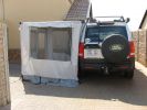
Awning248 viewsI have dual mounted awnings which can convert to tents if required. The outer side walls are an off the shelf purchase, but
the inner ( vehicle side )have to be made to spec.
|
|

100 viewsSORRY FOR THE LEVEL.....but
In the world there are only 2 OFF ROAD VEHICLE: the old italian Fiat Campagnola and new Land Rover Discovery3..
The 1st is dead, the 2nd is sold...Why the best have a problems?
|
|

A selection of fine vehicles!124 views
|
|
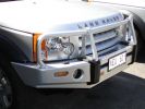
ARB Bull Bar Installation, Front side view. Colour coded to Vehicle.297 views
|
|
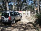
Locked gate and wire rope fence at start of Limeburners.68 views$11,000 fine if you are caught in a vehicle on the other side!
|
|

Papa King shows us why you never travel alone198 viewsAll of a sudden the sand became spongy, and Kingsley\'s vehicle just sunk in up to the chassis. Took the guys quite a while to dig and winch it out.
|
|
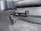
Base unit458 viewsFixed to seat base so it moves with the seat, two power supplies are needed to start up and shut down with the vehicle
|
|

The kids at Ruacana School, expedition vehicles in the background158 views
|
|
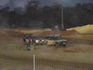
210 viewsLining up for the last two runs - only one make of vehicle left in the comp!
|
|
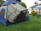
Tent showing vehicle 'sock'167 views
|
|

Photo showing inside sock.166 viewsThere is a double layer inside. Just like a conventional tent, the waterproof layer, then a flysheet. Both can be zipped/unzipped when vehicle is not in place.
|
|
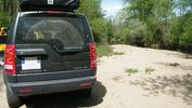
D3 Vehicle Sticker75 views
|
|
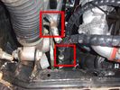
View of both hose connections to power steering system153 viewsBoth connections are shown. My friendly Qantas hydraulic hose expert cut off the elbow and modified it so I can re-install it to the PS rack before warranty work (and certainly before the vehicle is lifted off the body!!).
|
|
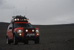
calendar entry 2009543 viewsHigh on the Iceland Interior - On the Road to Askja - G4 D3 Discovery V8 HSE - Team vehicle from 2006 G4 Stage 3/4 Bolivia -
|
|
added battery connector for charging direct from vehicle - the solar panel also plugs in here, so can be used for vehicle or trailer charging108 views
|
|

2008 GToN vehicle plaque107 viewsFrom 2008 GToN www.gton.co.uk
|
|

Guava Vehicle Conversions 210 views
|
|

Guava Vehicle Conversions 110 views
|
|

South African Disco 3 2007 model (VIN 7A) EGR valve Right hand side.46 viewsIt is still an EU3 spec vehicle, so the EGRs can be blanked off successfully.
|
|

Leopard21 viewsLR prototype electric vehicle - game viewer with TrailAir fitted
|
|

9 views
|
|
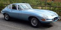
Jaguar E Type S1 4.2 Coupe6 viewsFactory restoration to near concourse condition almost complete. Disco 3 purchased as towing vehicle for shows.
|
|
Thread upload6 viewsImage uploaded in thread 186450
|
|
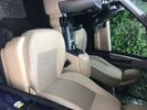
51 viewspictures on insidevehicle
|
|
Leopard23 viewsRear view of game viewer ( defender electric vehicle ) with trailair camera fitted.
|
|

O.M.G!117 viewsThe vehicle sits at an alarming angle on the edge of the slope
|
|
Furrow122 viewsThe rear tyre has descended into the furrow and the vehicle is now safer at last.
|
|
79 views
|
|
Thread upload22 viewsImage uploaded in thread 129760
|
|

Series LR at Oil Sands Plant in Northern Canada circa 1968747 viewsThis is an end of shift picture taken about 1968 at the Great Canadian Oil Sands (GCOS) plant while under construction in the Ft McMurray area of Northern Canada.
I was surprised to see the yellow coloured Series single cab hardtop pickup parked in about the centre of the picture. I would say it is one of the few on site as most vehicles were Chevrolet's, (as are the other three trucks elsewhere in the view). The yellow painted vehicles including the Land Rover are most likely Bechtel owned - not leased - yes, that long ago now.
|
|

102 views
|
|

Salisbury Plain301 viewsMy other club (Range Rover Register) had a plains day, ironically none of the 5 vehicles present were RR but 3 were at least from the same factory!
|
|
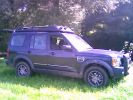
Goyt Valley Working Party Crew Vehicle149 views
|
|
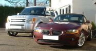
The Disco and the Z4!846 views2 of my current fleet of 3 vehicles...
|
|
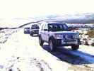
Great views, great vehicles.390 views
|
|

Land Rover Experience, Drive Your Own Day13 viewsDrive your own vehicle off road in thousands of acres of Peckforton Estate.
|
|

The perfect tow vehicle.17 views
|
|

Peckforton Castle. Drive your own day.14 viewsDrive your own vehicle in the wilds of Peckforton, Cheshire.
|
|

Installing Ballast Resistor to Vehicle loom164 views
|
|
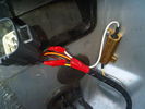
Installing Ballast Resistor to Vehicle loom173 views
|
|

Training Exercise235 viewsVehicle introduced to residual EQ liquefaction silt
|
|

Guest Vehicle Tracking - Day1 / Day2 Overlayed onto Google Earth153 views
|
|

Heavy vehicle and soft ground...336 views... Results were predictable. We got it out with the help of another Nyala.
|
|

You can see the winching vehicle here27 views
|
|
Training Snatch Strap Recovery, Vehicle intentionally bogged for the training exercise46 views
|
|
![Filename=IMG_0888[1].JPG
Filesize=106KB
Dimensions=1280x720
Date added=12.Dec 2016 IMG_0888[1].JPG](albums/userpics/19160/thumb_IMG_0888%5B1%5D.JPG)
Spotted9 viewsJLR Test vehicle
|
|

suspension 41 viewssuspension vehicle raising slowly
|
|

Under-vehicle wiring575 viewsUnder-vehicle wiring on Discovery 3
|
|
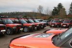
G4 2009 Vehicles197 views
|
|

Frontrunner Sump Guard Fitted12 viewsSGLD009
https://www.frontrunneroutfitters.com/en/be/protection-equipment/under-vehicle-protection/land-rover-discovery-2014-present-sump-guard-4-5mm-3cr12-stainless-steel-front-runner.html
|
|

\'Go Anywhere\' Vehicle meets \'No you\'re not\' Moody Cow133 views
|
|

tough Himba warrior next to an even tougher vehicle168 viewsPicture taken by Paulo Fernandes
|
|

JCB\'s High Mobility Utility Vehicle254 views
|
|

LA501-010 Technical Bulletin - Removal of Transit Wiper Blades at Vehicle Preparation63 views
|
|

9 views
|
|
45 views
|
|

LR Electric Trailer Brake C2590 Female Connector606 viewsThis female connector, C2590, located up above and near the brake pedal is for the Trailer Electric Brake Controller hookup.
The Black wire in the bottom right is pin #3, the ground. The Blue wire to the left is pin #6, the Trailer Brake Controller output going to the rear trailer socket.
The White #4 wire is the 30 amp fusible link, (Link 6E in the engine compartment junction box), for the Brake Controller 12VDC power feed from the battery. Note that this would make a pretty good power source for CB radios and the like if no electric trailer brakes were required.
Pin #5 is a Green wire from the stop lamp switch, (the control input for the Brake Controller).
This plug is standard on all NAS (LR3) vehicles, but unlikely to be found on the D3 spec units.
|
|
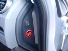
Air Suspension ECU Fuse 35P cut off switch.3820 viewsThis shows the SPST rocker switch mounted in the blank plate installed in lieu of a manual passenger side air bag shut down switch - now automatic via passenger seat pressure switch. Fuse 35P (5 amps) is located in the interior fuse box behind the lower glove box and protects the ignition power supply to the Air Suspension ECU. When the SPST switch is moved to the OFF position, the RAISE /LOWER switch on the centre console is not powered, and hence does not function. As such, some signals from the wheel height sensors and CPU are ignored. By itself however, removing F35P will probably not stop the 3 from self dropping, particularly after the engine is turned off.
Fuse F3E, (5 amps), located in the engine bay fuse box by the starting battery protects the circuit that provides feedback to the Air System ECU indicating that the Compressor Relay has successfully operated and that the Air Compressor is or should be operational, can also be removed, (but is probably not totally necessary), as it gets its power thru F26E. Hence Fuse F26E, (20 amp), also located in the engine compartment fuse box is the fuse that must be removed. This fuse protects the circuit that provides full time battery power to the Air System ECU. When in place, current thru the fuse powers the periodic re-levelling action, (usually lowering a bit with that brief air release noise), that often occurs when the vehicle is parked and the engine is off.
Removing F26E fuse will stop the auto levelling action and also inhibit any other down to the stops signals, (engine running or not). When F26E is removed, no power can flow thru to F3E, hence removing F3E is more for insurance than an absolute requirement. The same with F35P, removing F26E removes primary full time power from the Air Suspension ECU, and hence removing the F35P fuse should not really be required either as long as F26E has been removed.
|
|

Battery Maintainer pigtail sticking out of Grill726 viewsThis is all you see when everything is put back together - just the pigtail and Weather Pack blanking plug. Most often, I have it all tucked back behind the grill.
In winter, there may be a second cord hanging out as well - the 120 VAC power cord for the engine block heater, a tea kettle like element inserted in the engine block. NAS petrol V8's do not have the Fuel Burning Heater, (FBH), installed, but instead in cold area markets have the block heater element assembly available as a dealer installed option. There is an argument to say that the heating element is factory installed in all cold climate V8 gasoline engines, however the appropriate power cord is not. If true, this means that all one needs to purchase is the area specific power cord and plugging in / attachment to the engine block located block heater.
As such, you will often see a conventional 120VAC three prong power plug hanging loose out of the grill of most vehicles here in the wintertime. In summer, most drivers tuck the plug back behind the grill as it is no beauty mark.
|
|
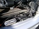
Battery Maintainer switching box plug and CTEK Multi US 3300 charger. 706 viewsThe CTEK Multi US 3300 maintainer is just sitting there for the picture. In addition to topping up both batteries, the CTEK can provide power such that if the batteries were completely dead, there would be power to the door locks and hence, one could most likely still gain access via the remote once the starting battery charged up a bit.
The Land Rover recommended method is via the hidden key hole which is mechanical, however that presumes the mechanism is not frozen from lack of use. As such, the manual lock should be exercised at least once a year to ensure that it still functions.
The blanking plug sitting on top of the plastic box is of the GM Weather Pack series. That is what I like to use for vehicle wiring that is subject to moisture, (or not).
|
|
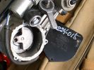
Compressor Con Rod Broken 1752 viewsThe model number of this compressor is RQG500060; the model number of my replacement compressor was LR015303, the unit that was apparently being installed on the D4 vehicles as of Spring 2010. As of Fall 2011, the new replacement part number is LR023964, the same as in the 4's.
Note the number hand written on the black plate. All the compressors seem to have some number hand written on them - hand built I presume, and every unit perhaps evolving a bit differently as LR struggles to build a compressor that will last. I guess Hitachi, (the manufacturer), should be given credit for that.
|
|
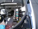
View from front left side looking towards rear aux battery compartment under cover 646 viewsAs there is no Fuel Burning Heater in the NAS V8 petrol vehicles, there is space available to install the FASKIT panel here. The piping is such that each air spring can be isolated from the air system and then filled one at a time manually via the Schrader valve. There are five Schrader valves and five shutoff valves. The fifth valve nearest the gauge controls air from the compressor, and can provide fill up air via a jumper fill line assuming the compressor is still operational.
|
|

NAS 7 Blade Round plus NAS 4 Pin Flat Vehicle end Socket527 viewsThis shows the function of each blade when looking into the connector at the vehicle end for the 7 pin NAS plug. The layout is the pin order for most new North American pickup trucks and the LR3/4.
The colour and gauge of the wires feeding into the back of the plug varies even within manufacturer model lines.
Also detailed is the flat 4 pin layout common on smaller trailers not having electric brakes. This includes most U-Haul rental trailers.
|
|

NAS 7 Pin Round Socket + 4 Pin Flat Socket oriented as installed.752 viewsThis is the layout you see when you look into the NAS Land Rover sockets as installed at the rear of the LR3/4. The flat 4 pin socket is located under the round socket.
Wiring order is relative to the slot on the round socket, and hence the same as the other jpg where the slot is shown at the top.
The CJB monitors the front and rear turn signal lamps and can detect if more than four lamps are fitted, (the side turn signal lamps are not monitored). This is another reason for using genuine LR bulbs as off shore bulbs can have varied and out of spec resistance values.
When a trailer is detected, the trailer warning indicator in the instrument cluster is supposed to flash green in synchronization with the turn signal indicators.
If one or more of the turn signal lamps on the vehicle or the trailer are defective, the trailer warning indicator will cease to flash any longer. This is to alert the driver to probably bulb failure.
If the trailer has LED lamps installed, and no LED adapter circuitry is used, most likely the trailer will not be sensed and systems such as the backup sensors will not be disabled.
|
|

Underhood Fuse and Relay Box drawing 3054 viewsShows the various fuse and relay locations. Fuse 3E, (5 amp), and Fuse 26E, (20 amp), as well as upgraded 70 amp Relay 7, part number YWB500220, locations are displayed. Relay 7 sends battery power to the compressor from the 60 amp fusible link called up as 10E. Fuse 26E is what provides full time always on battery power to the air suspension ECU and hence powers the auto level wakeup when the vehicle is shut down and say parked for the night. Removing F26E is the primary method to disable the air suspension system; Removing F35P is more if you want to experiment with it from inside.
I found it useful when I had a suspension problem, (actually a wheel alignment problem picked up by the steering wheel angle sensor), that only showed itself on the highway but allowed for no trouble light driving in the city. This was because in the city, the steering wheel was always in motion and rarely was the vehicle driven in a near straight line for very much distance.
|
|
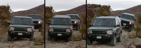
Smooth off road ride!399 viewsThis was the first time I took my LR3 off-road. I traded my Jeep Wrangler for this vehicle so I was used to heading into the rugged mountains. I was very amazed (as were my friends in their Jeeps) just how level the LR3 remained as I navigated over various dips and mounds. You can see the Cherokee behind me couldn't say the same.
|
|
![Filename=LR3_BMW_Ford_ZF_6HP26X-28X_Catalog_with_metal_pans_[1].pdf
Filesize=1194KB
Dimensions=320x240
Date added=26.May 2011 LR3_BMW_Ford_ZF_6HP26X-28X_Catalog_with_metal_pans_[1].pdf](images/thumb_pdf.jpg)
ZF 6HP26X and 6HP28X transmission parts showing various pans2814 viewsThis 42 page pdf is probably the most informative of all the material in this album. It is called a spare parts catalog but is much more than that. The material is specifically for the X variety of ZF six speed transmissions that are in the Land Rover 4WD / AWD models as well as BMW and Ford AWD vehicles.
|
|

LR3 Brake Wear Sensor Wiring1517 viewsThis 1 page wiring diagram pdf shows that both the front and rear brake pad wear sensors are part of a closed series circuit to ground.
In operation, when all is good, the series circuit is grounded and the amber brake wear warning indicator on the instrument panel is not illuminated.
When the pads on one wheel, either the left front, or right rear, become too worn, the respective sensor is "cut" which results in an open circuit condition. This causes the dash brake wear indicator to illuminate.
The circuit is like the old style Christmas light strings where one burned out bulb caused the whole string to go out.
A quick field fix to get the dash light to extinguish in lieu of replacing the sensor and pads etc is to disconnect the brake pad wear sensor and short across the two open conductors of the vehicle side connector plug. This of course means you now have a normal vehicle, one of the thousands that do not feature brake pad wear information systems.
|
|

Stop Light Lamp Circuit pdf2491 viewsThis pdf shows the brake light circuit for the NAS LR3.
Note that power for the brake light bulbs can come either thru the brake light switch power feed /contacts plus also from the Hill Decent Control, (HDC), system relay located within the Central Junction Box, (CJB) - yes two separate sources of power for the brake light bulbs. This would tend to explain how a brake light circuit concern shows up as a hill decent fault message; also why lesser vehicles without hill decent braking mechanisms, (HDC), never display this sort problem when a brake light bulb or switch acts up. You never have a problem related to a system that does not exist.
Additional evidence of the relationship of the HDC and the tail light circuit is demonstrated by when the HDC actually acts to slow the 3 down, the brake lights automatically illuminate even if the slowing action was merely retarding the engine speed or shifting to a lower gear, (in other words, no foot on the brake pedal).
There is also a tie in to the Cruise Control and hence a failing brake light switch can affect cruise operation or just create false Cruise Control messages. To further complicate the issue, while there are no messages generated, operation of the radiator electro viscous fan can also be negatively affected by the fouled set of secondary contacts within the brake light switch. This is all because the NC contacts within the brake switch send misleading messages to the ECU.
While the ground wire design is similar to other vehicles, note the grounds for the brake light filament and the reverse light filament are common on each side. That means that if one has a non functioning brake light on one side, the reverse light may not also work or that some problem with the reverse lights could back feed into the brake lights. This situation while unusual, can result when grounds are corroded probably due to swimming in rivers and creeks or just routine driving in a marine environment.
|
|

LTB00062 - Technical Bulletin - IDS Vehicle Reset Application83 views
|
|

Thread upload47 viewsImage uploaded in thread 134203
|
|

Lug Nut part number RRD500290 outline sketch541 viewsThis single sheet pdf provides dimensions of the LR part number RRD500290 lug nut on vehicles from MY 2005 to 2008, (up to VIN 8A450459). From VIN 8A450460, the part number is RRD500590.
Visually, there is no apparent difference between the two part numbers. The dimensions appear identical as well. The shape, size, and profile of the Stainless Steel "hat" appears identical.
There are I presume differences in metallurgy to reduce corrosion and swelling of the hat or perhaps better sealing between the inside surface of the hat and the steel of the lug nut body. The reality is the differences are not immediately obvious however.
A 22 mm six point half inch or larger socket drive fits over the lug nuts. I use a nominal 36" long breaker bar with the 22mm socket - any shorter bar, best you be in shape. Depending upon your source, for both alloy and steel wheels, the lug nut torque value appears to be 103 lbf ft, (140 Nm); others suggest first tighten to 96 and then finish at 110 lbf ft, (130 and 150 Nm).
|
|
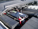
Main starting battery showing 1/2" hole drilled for power cable egress909 viewsView of OEM battery in Left Hand Drive LR3. This is supposed to be a Battery Group BCI 49 or H8 sized battery but in reality is the slightly shorter BCI 94R or H7 battery that fits easier lengthwise, (12 3/8" vs 14").
Note the 10mm hole drilled in plastic of surround to allow for entry of main power cable that runs between batteries. The cable bolts to a spare 6mm threaded hole in the OEM battery cable end; the light gauge wire runs to the front of vehicle to a connector for the CTEK MULTI US 3300 charger. Coloured felts, (red and green), are a material treated to reduce battery post corrosion. The OEM battery ground cable is only about a foot long and runs to an 8mm stud located on the inner fender just to the rear of the fuse case.
|
|

Maintenance Fluid Specifications for Legacy LR Vehicles175 viewsMaintenance Fluid Specifications for Legacy LR Vehicles1
|
|

NAS Trailer Wiring Colour Code366 viewsThis is a common wiring colour code for trailer wiring in North America. Some vehicle manufacturers follow the code for at least some of the functions.
|
|
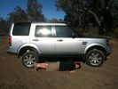
164 viewssuspension extension mode... 6\'3" son could have crawled under the vehicle easily.
|
|
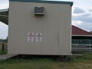
Parking Near Saleyards at Warwick154 viewsPrompted by the photo of generous parking at Walmart (USA), see how we do it in Australia. Trick, your vehicle must be narrower than about 100mm or a 2 dimensional facsimile only.
|
|

Thread upload5 viewsImage uploaded in thread 200758
|
|

11 views
|
|
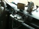
Lead Vehicle253 views
|
|
2008/09 Vehicle at Eastnor191 views
|
|
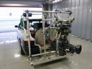
Film tracking vehicle F1 testing91 views
|
|
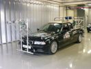
Film tracking vehicle F1 testing81 views
|
|
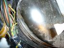
firewall plug run933 viewsThis is the engine side view, of where to poke the hole with a screwdriver to make a hole into the vehicle. You can barely see the edge of the hole. Note: The Rubber plug should be removed for this operation.
|
|
firewall plug run920 viewsHow to get the cable from the engine bay to the rear of the vehicle.
|
|
Wire Run670 viewsThis is the inside the vehicle view of the hole, to run the feed wire through the firewall.
|
|
firewall plug run855 viewsThrough the firewall to the right of the brake master cylinder. On left hand drive, this hole would be closest to the outside edge of vehicle.
|
|

CALENDAR 2011286 viewsTaken at the end of an extremely hot day in Morocco. Slimer, and Gareths vehicles. We stopped at an Auberge on the way to Zagora. The sky was an angry shade of yellow, and minutes later a spectacular storm raged. The owner of the auberge said it was the first rain in 3 months.
|
|
Suits the vehicle perfectly141 views
|
|
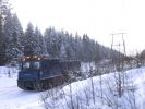
437 viewsFinnish (ex?) military snow vehicle.
|
|
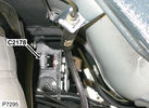
C2178 Module-Parking brake172 viewsPart No.: YPC801020
Colour: BLACK
Cavities: 32WY
Harness: CHASSIS HARNESS
Location: Beneath center of vehicle
|
|

FormulaShell Multi-Vehicle Automatic Transmission Fluid79 views
|
|

cross axle much? and maybe another member24 viewsdo you recognise the other vehicle?
|
|

Meals-On-Wheels!234 viewsOut with the Bux & Oxon Response Grp (BORG) delivering meals-on-wheels around Aylesbury, Wendover, High Wycombe & Chesham. There was about 8 of us out. Some escorted the vans, others took the meals in their own vehicles.I was in the latter catergory & the car smelt lovely, felt very hungry by the end!
|
|
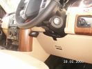
236 viewsVehicle Unit Display held on with Velcro, easily removable
|
|
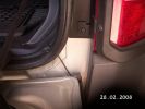
233 viewsRouting of the Trailer unit antennae through the rear door rubber & behind the bumper on the outside of the vehicle
|
|
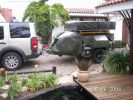
Stone Protection364 viewsCover fitted over front of trailer to minimize stones deflected onto rear of vehicle
|
|

Thread upload15 viewsImage uploaded in thread 164415
|
|
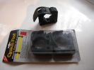
Quick Fists Tool fastners for vehicles90 views
|
|
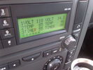
Voltage Display Page Radio Head Unit 118 14.2840 viewsThis shows the voltage/temperature/timer display page within the 6CD-465 radio head. There is a second file within this album, a doc file, that outlines the procedure to access the diagnostics.
The 14.1 volts number was the approximate vehicle system voltage with the engine running; the 118 number infers 11.8 volts which is the low power infotainment system shutdown cutoff voltage. The factory default setting is 135 or about 13.5 volts. By holding the keypad 1 button down, the 3 digit volts numbers will decrease 001 at a time until the keypad 1 button is released. Decreasing the number from 135 to some lower number should increase the time the system will remain on with the engine off.
The TEMP numbers refer to Fuel Burning Heater, (FBH), temperature values. 85 is apparently a high limit and 46 was the number when the jpg was taken. This number varies and given that there is no diesel fueled FBH in our NAS petrol engine vehicles, what the value refers to is unclear. The TIMER numbers also relate to the diesel fuel burning engine heater and perhaps make more sense being 00.
|
|
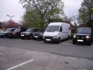
D3 line up at the Red Lion in High Lane164 viewsAndrewS\'s Merceds Sprinter Van (fastest vehicle on the road) spoils the line-up in the car park
|
|
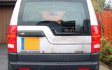
Rev Camera Rear No Plate lamp rear of Vehicle126 views
|
|
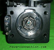
NAS 7 pin + NAS 4 pin Flat Trailer Socket308 viewsThis is the vehicle end of the NAS trailer harness that is located behind the removable plate centered within the rear bumper by the towing loop. Re the four pin flat connector, from the bottom, the exposed bare lower pin is the ground, usually the White wire on a NAS trailer. The next pin up is normally a Brown wire on a trailer and is for the Tail Lights. The third pin, normally a Yellow wire, is the left signal light; the top pin, normally a Green coloured wire, is the right signal light.
Re the round connector, from the notch in the plastic surround, clockwise, the first blade is ignition controlled +12VDC battery power, (only alive when engine running), and on the Land Rover factory harness is an Orange wire; on a NAS trailer, usually Red but perhaps a Black wire.
Next blade clockwise at 3:00 o'clock above, is the Right Turn signal light, a Green wire on the LR harness, and also on a NAS trailer.
At 5:00 o'clock, the next blade is for the Electric Brakes and is Blue on both the LR harness and on a NAS trailer.
The Ground wire is next, White on both the LR harness and on a trailer.
At 9:00 o'clock above, is the Left Turn signal, Yellow on both the LR harness and on a trailer.
The last blade to the left of the line up notch is the Tail Light circuit. On the LR harness, the wire colour is Brown with two White stripes and on a NAS trailer, Brown.
The centre pin is for the Reverse Back Up lights and is Black on the LR harness and often Purple on NAS trailer wiring but can be Black also.
Note that when the socket assembly is installed on the 3, the notch in the plastic surround is on the left - that is rotated 90 degrees anticlockwise to the picture above. In other words, When installed on the 3, the 4 pin flat connector lays horizontal and is located below the round socket.
|
|

Towing Info121 views
|
|
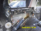
LHS rear quarter panel59 viewsThis is what it looks like behind my vehicles rear quester panel
|
|
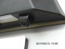
Tailgate Camera located above license plate.598 viewsThis aftermarket camera is mounted on my 2005 LR3 in almost the same location as the factory cameras. The factory units are mounted somewhat more forward closer to the metal of the tail gate and I could have done the same as well.
Note that the camera above is aimed a bit towards the centreline of the vehicle per the factory install.
|
|

compressor repair tsb162 views
|
|

Thread upload26 viewsImage uploaded in thread 151493
|
|

Thread upload33 viewsImage uploaded in thread 133692
|
|
select by vehicle145 views
|
|

Over 50 CT vehicles - A great sight!137 views
|
|
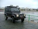
90 Defender rapid response vehicle, low profile light bar243 views
|
|

Thread upload5 viewsImage uploaded in new thread
|
|

TA04-303 - Technical Bulletin - LA01 - Vehicle Preparation Coolant Check227 views
|
|
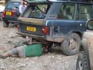
Bust Petrol Tank198 viewsThis RR Classic\'s petrol tank got ruptured coming down Pimdale - this is the rush to collect and distribute the contents to other vehicles!
|
|
![Filename=Technical Service Bulletin SB034 SB036 Vehicle Enhancement Program[1].pdf
Filesize=959KB
Dimensions=0x0
Date added=17.Jun 2010 Technical Service Bulletin SB034 SB036 Vehicle Enhancement Program[1].pdf](images/thumb_pdf.jpg)
Technical Service Bulletin SB034 SB036 Vehicle Enhancement Program2390 viewsOn page 6 and following are the Land Rover service bulletin instructions as to how to install delivery valve and exhaust valve repair kit JPO500010; also a list of previous compressor model numbers as related to the 3. The new delivery valve is easy to install, the exhaust, not so easy. Note that this in not the more recent TSB that reduced the operating pressure of the compressor via a software fix and also recommended replacement of the air compressor 70 amp relay. See the F35 album near the bottom for the relay material.
|
|

Tekonsha Ford Brake Controller Adapter part number 3035-P274 viewsThis is the adapter cable between the Brake Controller and the existing C2590 female plug located near the brake pedal on NAS spec LR3's. The flat 4 pin plug of the adapter cable connects to the Controller; the rectangular 6 hole male plug to C2590.
There are only four conductors in the adapter cable, but one will see five pins within the Land Rover C2590 plug. The #2 pin is not required for the NAS setup. #2 pin is the circuit between the head lamp switch and vehicle side running lamps required in the civilized world.
The single pin at the bottom in the picture is #3 and on the Land Rover, a Black wire tied to ground. The other pin at the bottom and across to the left is #6, and Blue on the Land Rover. This is the Brake Controller output to the trailer socket at the rear.
#4 is the pin at the top left, and is a White coloured wire from the battery. Pin #5 is from the stop light switch, and is Green on the Land Rover.
Note that the adapter cable colours do not necessarily follow all the above referenced Land Rover colours.
|
|

The Disco 3 the day I bought it74 viewsSince then here's what's been done
1) New slotted and dimpled EBC rotors and Pads
2) Rover Specialties rock sliders
3) Clear color side markers
4) Front & Rear LR lamp guards
5) Rebuilt both of my Non working Key FOBS by replacing batteries. - I can't believe I didn't even check these when I bought the vehicle.
6) Changed the LR3 emblem to Discovery 3
7) Terrafirma Front Skid Plate
8) Tactical 4x4 Gas Tank Guard
9) ASFIR Rear Diff Guard
10) Here are the things now mounted on Roof Rack
- Full size 18" MTR/Kevlar
- (2) 5 Gallon Jerry Cans mounted in Front Runner holder
- 60" Hi-Lift X-treme Jack
- Shovel
- Magnetic CB Antennae
|
|

Thread upload3 viewsImage uploaded in new thread
|
|
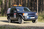
Land Rover Discovery 359 viewsLand Rover Discovery 3 used as spectator control vehicle on 2011 Trackrod Rally in Yorkshire
|
|
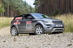
Range Rover Evoque 88 viewsRange Rover Evoque used as spectator control vehicle on 2011 Trackrod Rally in Yorkshire
|
|
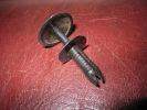
Two-part trim clip464 viewsThis is what I used to fix the Large Rear Mud flaps instead of my first attempt with screws - these actually cameof the vehicle when I fitted RLD's rock sliders
|
|
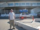
Noel\'s been admiring the Tunisian Vehicle Loading technique119 views
|
|

The vehicle line-up outside the Hotel in Matmata117 views
|
|

Thread upload15 viewsImage uploaded in thread 147133
|
|
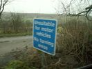
Unsuitable for motor vehicles no turning21 views
|
|

Camel Trophy 1996 Kalermantan 19 viewsAll the vehicles assembled at hotel ready for there crews, shiny and new
|
|

Varta Battery Dimension chart570 viewsThis pdf provides Varta dimensions for among others, the E12V75N, (old DIN H6 or 85605 or BCI Group 48 size). This appears to be a deep cycle battery and the choice for many re the Aux battery install as long as you are willing to grind away the angled nibs at the bottom front of the battery surround. My choice was a shallow cycle battery intended for cold weather related engine starting rather than winch use.
Note the pdf Varta batteries are all deep cycle batteries suitable for running fridges, winches etc, rather than for engine starting and hence a good Aux battery if those are the intended uses rather than engine starting.
Varta now makes a Varta G14 with AGM technology and known as a Stop Start Plus battery. It is 95Ah, CCA of 850A; length 353mm; Width 175mm; Height 790mm and is specific for these newer stop start vehicles such as some D4's. For the 3's, one is still probably better off with an H8 sized battery but of the older Wet Flooded Lead Acid type and battery caps rather than a sealed AGM.
The Land Rover part number for the recommended battery is LR033179.
|
|

Reach for a dream vehicle booking form.35 views
|
|

vehicle dynamic suspension106 views
|
|
141 views
|
|
134 views
|
|
143 views
|
|

136 views
|
|
140 views
|
|
159 views
|
|
143 views
|
|
131 views
|
|
134 views
|
|
139 views
|
|
153 views
|
|
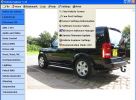
vehicle explorer settings136 views
|
|

Configurations90 views
|
|

Thread upload1 viewsImage uploaded in thread 190501
|
|

Thread upload25 viewsImage uploaded in new thread
|
|

LR3 Vehicle Dynamic Suspension109 viewsLR3 Vehicle Dynamic Suspension wiring diagram
|
|

Suspension system fault codes and diagnostics32 views
|
|

Thread upload12 viewsImage uploaded in thread 170425
|
|

20 views
|
|
Thread upload5 viewsImage uploaded in thread 168779
|
|

Vehicle Maintenance Log for LR3/4 D3/4 or other1135 viewsThis is a Excel file that you can download and then modify to suit. It is very simple, but allows me to keep track of most maintenance and fixes etc on my LR3. All columns and rows and boxes can be edited.
I did not erase any data in the various boxes so you could see how I am using it - again not very fancy but it works for me. Under the brakes column, one will see f6 r5 which is how I keep track of the condition of the brake pads. The dealer records the pad thickness at each oil change so that is where the numbers come from.
f is for Front Pads, 6 is for 6mm; r is for Rear pads, 5 is for 5 mm. New pads are about 10 mm; replacement is at 3 mm or less. The amber coloured brake wear dash warning light should come on at about 2 mm.
|
|
50 views
|
|

Voss B203 Fitting Install957 viewsNote on the first page, the reference to DIN 73378 and D74324 and also PA11 and PA12 material when referencing suitable spec nylon (polyamide) air line for motor vehicles. I think some of the 6mm fittings used on the 3 for the valve blocks are the System 203 type and called up as Land Rover part number RQC 000030. The Voss part number is I believe 5 2 03 11 01 00.
|
|

Thread upload3 viewsImage uploaded in thread 181177
|
|

142 views1971 Mini Moke (4x4 Recovery vehicle & still loved)
|
|

ZF LifeguardFluid6 transmission oil.1397 viewsThis is an interesting pdf in that under the ZF 6HP26 six speed section, it provides the various automobile manufacturer part numbers for their version of the appropriate tranny oil, all of which seems to be the LifeguardFluid6 oil, ZF part number S671 090 255. Note the fine print and do not confuse it with the LifeguardFluid6 Plus oil for vehicles with the Torsen AWD setup such as the Audi Quattro, VW 4Motion vehicles and I think the BMW FF Range Rovers of an earlier time.
Also of interest at the bottom of the pdf is the recommendation for replacing the transmission oil "between 80,000 km and 120,000 km or 8 years, depending on the load." I also do not see any reference to "sealed for life" but almost as optimistic, "maintenance free" but with the proviso "intended for normal operating conditions". This would most typically be the Sandringham Castle Grounds in the UK rather than Cape York, QLD.
|
|
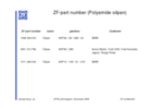
ZF Plastic Pan / Filter part numbers852 viewsZF, not Land Rover, part numbers for the various types of plastic pan depending upon vehicle manufacturer. The BMW pan is apparently different from the Land Rover pan even though the transmissions are 6HP26 units. No wonder each manufacturer has his own oil - maybe it is different as well. What I find interesting is the mention of Ford Australia and Ford USA separately rather than just Ford.
|
|

Troubleshooting pdf re Mechatronic unit on 6HP26 ZF Automatic 2144 viewsThis 21 page pdf shows possible problems within the Mechatronic unit of the ZF 6HP26 six speed automatic. On page 19/21 is a drawing showing how all the various control circuits interface with the vehicle.
Of particular interest were comments with regards to fine metal contamination of various electrical contacts. This is probably why a mere oil change can improve the operation of the transmission - reduced conductivity of the oil.
|
|
|
|
|
|