| Search results - "aux" |
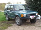
51 viewsD44 front winch bumper. Ali washer bottle. D44 rear h/d bumper. centre diff lock. 235x85x16 pirelli muds. OME +2" springs & shocks. front diff guard. side tree bars. wired for roof CB. Aux fuse block. safari snorkel. extended wading tubes. the list goes on...
|
|
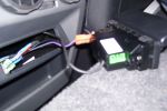
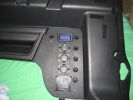
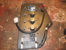
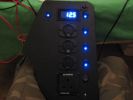
Centre console 12v & aux panel146 views
|
|
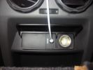
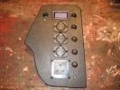
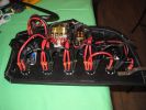
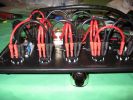
Centre console 12v & aux panel fitted281 views
|
|
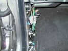
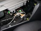
N/S Kickpanel wiring harness for AUX input4291 views
|
|

The ipod connected to AUX input3763 views
|
|
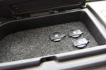
Aux 12v 67 views
|
|
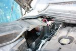
120 viewsModified aux battery box cover with shape of battery to battery cable. I also removed the tab which was fouling my traxide brain mounting bolts.
|
|
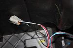
109 viewsThis is the plug for the accessory socket at the rear of the cubby box. On commercial D3 such as this one, there is no accessory socket so this plug is unused. I tapped into the 12V wire as an ignition feed. This will feed a relay coil which opens up power from the aux battery. Like this I can still retro fit and make use of the accessory socket later on.
|
|
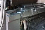
91 views12V socket done. This is permanently powered by the Aux battery. Another one was done on the other side, though that one required drilling the hole with a 29mm hole saw as there wasn't an unused hole on that side.
|
|

connection the gps on the aux stereo's29 views
|
|
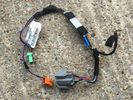
Rear console Loom AH22-14K042-CB - Arm rest for aux audio fridge for fridge14 views
|
|

Rear Area Climate Control System1161 viewsThis 14 page pdf describes how the rear heating AC system is supposed to operate in conjunction with the front system.
The air transfer ducts are shown as coloured sketches as is the air flow within the rear blower setup.
|
|

Thread upload11 viewsImage uploaded in thread 188531
|
|
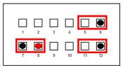
AUX Connection86 views
|
|
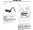
359 views
|
|
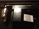
LR Aux Panel (rear)61 viewsBack of LR rear aux input panel
|
|
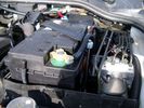
Aux Battery showing ground cable bolt "upside" down 1577 viewsIn order to obtain sufficient height clearance to get the plastic cover back on, I had to install the ground cable to the underside of the battery post connector.
Note the battery vent hose, (approx 5 ft required) is run down into where the windshield washer fluid container is located. There is not much electrical or metal in that area to be corroded by battery gas plus the open end of the vent hose tends to be protected from dirt and stays clean as well.
|
|
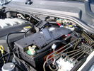
BCI Group 40R Deka 640RMF battery showing vent hose run forward to windshield washer reservoir area 1430 viewsRecessed post "Euro profile" battery to "match" OEM and stock Land Rover bracket; note that the Traxide SC80-LR module is mounted at an angle to allow for the main cable to sit under the cover so cover still closes.
The battery is a nominal 7", (180mm), high, but sits on a 1" battery spacer set under to raise the bottom front end of the battery such that the approx 11", (290 mm), length of the BCI 40R battery rises above the angled plastic nibs at the forward end bottom of the case front; hence sufficient space, (1/4", 5mm) remains at the brake reservoir end.
Also the 40R battery does not have hold down "flanges" on each end; on the sides yes, but not the ends so no additional length is required.
When I had to replace the 40R, this time I installed the shorter, (9.625"), taller, (7.5") Interstate BCI 47 / DIN H5 battery which eliminated the spacer on the bottom and better fit the stock LR tie down bolt lengths. Deka also has a BCI 47 / DIN H5 that would work fine as well.
|
|

Aux Climate Control111 views
|
|
436 views
|
|
288 views
|
|
229 views
|
|
620 views
|
|
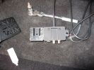
LR Aux Panel (front)68 viewsLR rear aux panel
|
|
1074 views
|
|
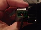
Aux Input Wiring Harness69 viewsUsed a modified PC CD interface cable to connect to stock female harness. Pins 3(R), 4(L), 5(G)
|
|
270 views
|
|

231 views
|
|
178 views
|
|
182 views
|
|
193 views
|
|
194 views
|
|
204 views
|
|

190 views
|
|
190 views
|
|
192 views
|
|
318 views
|
|
340 views
|
|
291 views
|
|
250 views
|
|
236 views
|
|
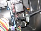
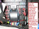
aux sockets relay - remove the relay and put in link wire 192 views
|
|
509 views
|
|
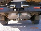
491 views
|
|
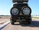
682 views
|
|
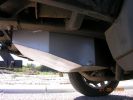
569 views
|
|
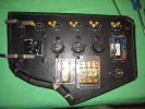
301 views
|
|
417 views
|
|
262 views
|
|
263 views
|
|

92 views
|
|

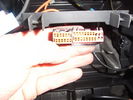
AUX wires?25 viewsIs this the AUX wires to tap into?
|
|

Thread upload15 viewsImage uploaded in thread 125443
|
|

Thread upload0 viewsImage uploaded in thread 209494
|
|

Thread upload1 viewsImage uploaded in thread 209494
|
|

D4 Auxilliary or Second Battery installed in Aux Battery Box216 views
|
|
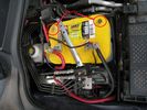
D4 Auxilliary or Second Battery installed in Aux Battery Box, Vents Circled192 views
|
|

157 viewsAux Cover R/Hand
|
|

auxiliary climate control51 views
|
|

Thread upload0 viewsImage uploaded in thread 198799
|
|

Thread upload2 viewsImage uploaded in thread 198799
|
|

Thread upload13 viewsImage uploaded in thread 138228
|
|
88 views
|
|

Aux85 views
|
|
D4 Auxiliary Light Switch351 views
|
|

26 views
|
|

Thread upload25 viewsImage uploaded in thread 106207
|
|
Thread upload82 viewsImage uploaded in thread 52879
|
|

Thread upload5 viewsImage uploaded in new thread
|
|

Thread upload21 viewsImage uploaded in thread 106207
|
|

Thread upload2 viewsImage uploaded in thread 198799
|
|
151 views
|
|
Thread upload4 viewsImage uploaded in new thread
|
|
Thread upload11 viewsImage uploaded in thread 17945
|
|

Thread upload1 viewsImage uploaded in new thread
|
|

Thread upload13 viewsImage uploaded in thread 130027
|
|
Thread upload33 viewsImage uploaded in new thread
|
|
Thread upload2 viewsImage uploaded in new thread
|
|
Thread upload1 viewsImage uploaded in new thread
|
|
Thread upload6 viewsImage uploaded in new thread
|
|

Thread upload17 viewsImage uploaded in new thread
|
|
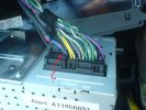
base radio aux connections666 views
|
|

Caterpillar Battery Size cross reference chart and battery profiles including post layout753 viewsThis pdf has a dimension, (metric and inches), cross reference chart plus another sheet that provides BCI and DIN cross reference numbers and shows post locations plus bottom ridge tie down locations, (or the lack of).
This data was for me, hard to find, and helps one in selecting a suitable physical size of Aux battery for the space available.
|
|
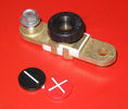
Battery Disconnect side post with + & - caps, top view617 viewsThis disconnect is designed for side post batteries. It can be used on either the + or - terminals. It can also be installed at the "other" end of the battery cable as well. In my install of the Aux battery, I installed this on the negative ground cable where the cable attaches to the body sheet metal. I have never used it but it seemed like a good idea at the time. The main battery hookup is pure stock.
For the hot side of the Aux battery, an Anderson PowerPole was used inline for the cable between the Aux and connecting to the spare bolt hole at the + post of the Main battery cable.
|
|
Aux Input Panel Box59 viewsCorrect Part Number
|
|

Thread upload4 viewsImage uploaded in new thread
|
|

Thread upload12 viewsImage uploaded in new thread
|
|
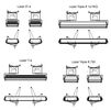
Thread upload4 viewsImage uploaded in thread 204881
|
|
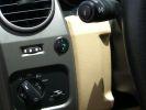
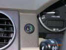
Long Ranger auxilairy fuel tank pump switch and tank gauge308 viewsFitted to the right of the air vent thumbwheel, the neat combination switch and gauge take sup no room at all. Switch locks on or off, but no pump running warning lamp! Contents of the tank are indicated by 5 LEDS, 4 green and 1 red for full, 3/4, 1/2, 1/4 and empty. Pump transfer rate of just 2 litres p/min is disappointing. I transfer on the move when main tank is at 1/4.
|
|
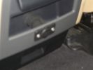
Auxiliary power sockets - TracTronics, Australia383 viewsA complete kit including two outlets, wiring etc connected to auxiliary Optima Blue top battery using their very effective SC40 split charge relay. One outlet between rear and front seats, and 2nd alongside loadspace 12v outlet, enables fridge to run when engine is not running, without affecting start capacity or vehicle functions.
|
|
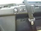
TracTronics loadspace power socket 382 viewsThe 2nd power socket fitted alongside the original in the loadspace runs off the auxiliary Optima Bluetop battery to run a fridge when engine is not running. No more starting worries!
|
|
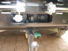
LR towing electrics pack 12N/12S313 viewsThe LR trailer electrics fitted before the Kaymar bumper and spare wheel carriers required no modifications are perfectly accessible. Good strong recovery point between the sockets too. The swing awau wheel carrier securing latches can be seen quite clearly here. Long Ranger tank (painted black) nestles where orignal spare was fitted.
|
|
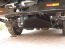
LongRanger auxiliary fuel tank358 viewsThe LR fuel tank imported from ARB in Australia with its 115 litre capacity has more than doubled the range of the car. This is important in the desert where fuel consumption increases at times to 10mpg or less. On a cruise on highways, the car now has a range approaching 850 miles. The tank fits neatly, has not affected handling in a detectable way apart from over speed humps, when a little more bounce from the rear suspension is detected! Suspension copes with the additonal loads without any problem.
|
|
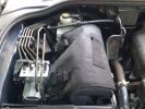
110 viewsTFC compressor in auxillary battery box
|
|
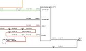
D4 Aux Lights Switch Wiring Diag80 views
|
|

Deka Battery Dimension Data615 viewsThe battery size that I installed for my auxiliary was a BCI 40R battery as it was for me the easiest to fit and was also a cranking battery. The case profile was such that no tie down fins were located on either bottom end, (sides yes), and length wise, it was only about 11" (290 mm) long. As such, I did not have to grind the nibs at the front bottom of the plastic surround.
I did however raise the bottom of the battery above the angled nibs as I set the battery on a 1" (25mm) high plastic spacer. The total height, (battery plus spacer), was about 8" (200mm) so the battery top still fit under the Land Rover factory cover.
For the Aux battery, when I replaced the 40R, I installed an Interstate BCI 47 which is similar in size to a DIN H5. I was therefore able to eliminate the vertical spacer as the Group 47/H5 is the same height as the DIN H7/H8 stock LR spec starting battery. As such, the standard battery tie down bolts can be used without modification. The Group 47 battery is 9 11/16" long x 6 7/8" wide x 7 1/2" (190mm) high.
|
|

Auxiliary Climate control53 views
|
|

Aux Climate Control9 views
|
|
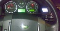
ipod detail159 viewsipod mounted without lr´s ipod kit. A cable cames from HK back aux input.
|
|
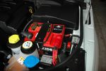
Aux Battery29 views
|
|
Doges de Bordeaux31 views
|
|
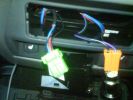
AUX connector253 views
|
|
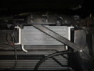
Aux transmission oil cooler116 views
|
|
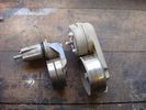
aux belt roller + tensioner53 views
|
|

upper aux. belt roller39 views
|
|

aux belt upper roller - cap removed64 views
|
|

Upper aux belt roller removed50 views
|
|
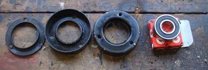
upper aux belt roller for re-assembly54 views
|
|
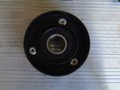
aux belt roller re-assembled50 views
|
|
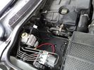
73 viewsAux battery tray - I found out you can remove the side as well as the top cover of the compartment.
|
|
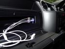
iPod connectors17 viewsAux video and Audio inputs (for nav screen) and usb charge point in upper glovebox
|
|
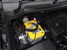
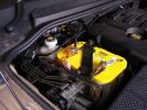
Optima Yellow Top16 viewsAGM auxiliary battery in second battery compartment
|
|
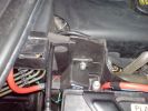
aux battery 120amp relay213 views
|
|
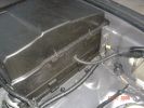
Aux Battery Cover167 views
|
|
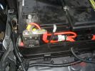
Aux to Main Battery201 views
|
|
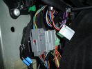
Aux connector in passenger footwell (disconnected)140 views
|
|
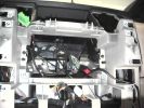
wires for aux input, 12 volt andmicrophone through the cubby floor662 views
|
|
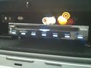
DVD Player63 viewsVeba DVD Player fitted into top glove box, AUX in for connection of Ipod, Games COnsoles etc. Remote control with sensor mounted by rear view mirror.
|
|

371 views
|
|
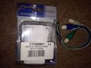
Thread upload23 viewsImage uploaded in new thread
|
|

Searching for the correct Aux socket in passenger footwell180 views
|
|
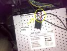
103 viewsaux in connection
|
|

The new Aux Battery charger for the D3 !196 views
|
|
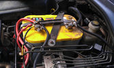
The auxiliary battery21 viewsThe auxiliary battery in the bay.
As the wiring diagram I made shows, there's a wire leading to the fuse box in the rear. (is going through the key-switch)
The second one is going to the fog lights. The smaller cables which should be connected to the head-lights, are connected to the battery.
The third one is going to the compressor (via a switch) (sits before the key-switch)
A fourth one is going to the CB and battery check display (sits before the key-switch)
|
|

Close up - Solenoid16 viewsA close up of the solenoid which is installed close to the auxiliary battery bay.
|
|

Close up - key removed18 viewsIn the center is the added switch with removable key.
Here the key is removed.
This is to add an additional 'protection' from discharging the auxiliary battery in case other people are working on the car and accidentally switches on any electrical bit :)
|
|
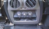
12V outlets for the 2nd row13 viewsI used a part of the old front (which was broke) to cut out a 'mount' for three 12V outlets for the second row.
The outer outlets are switched on whenever the ignition is on as I used the connector that originally was out there.
The middle outlet is connected to the auxiliary battery and is switched on/off through a rocker switch in the central console. (other picture)
This middle one is going to be used for our small fridge that usually resides just there when we're on holiday.
|
|
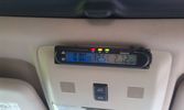
Battery check display15 viewsI mounted a digital battery display in order to see the voltage on the auxiliary battery.
There's also a thermometer which gives the inner and outer (via a side switch) values.
The display is switched on/off via another rocker switch.
|
|
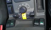
The on/off switch for the battery display22 viewsThe right inner switch 'powers' the auxiliary battery display. I might use that one to power on/off the driving camera (which will be arriving soon) as well. Although I'm not sure yet.
|
|
Solenoid engaged15 viewsAfter the engine's running for 5 minutes, the solenoid gets engaged and starts charging the auxiliary battery.
|
|
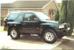
1994 Vauxhall Frontera, worst car I ever had the stupidity to buy108 views
|
|
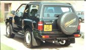
1994 Vauxhall Frontera, how they ever got away with calling it a \'Sport\'!119 views
|
|

iPod aux connection15 viewsPictures of installation of iPod into d3 cd player
|
|

Over the sands97 viewsInitially tried the car with all up weight - full auxiliary (115L)and main (85L) fuel tanks, dual spare wheels, and roof rack. Car had a marked tendency to tail end slide when on side slopes, especially in soft - really soft sand.
|
|

iPod connection12 viewsPictures of plug pins break in solder and finished installation Jack lead iPod connection
|
|
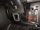
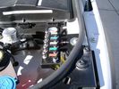
Aux battery fuse box18 viewsMy install of a fuse box.
|
|

Aux battery fuse box19 viewsClose up of fuse box
|
|

Aux Battery1054 viewsShows the aux 65Ah battery in place, top left of the picture is the 100amp circuit breaker feeding items sutch as , inverter, sub bass amplifiers, computer.
|
|

Aux Battery918 viewsShopwing the addition of the 35mm2 cable going to the split charge relay
|
|
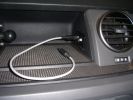
Connectors for Sound out and DC in181 viewsSound out (cable inserted) - connected to Aux connector in passenger footwell.DC in connector is always live
|
|

aux power and ashtray section660 views
|
|
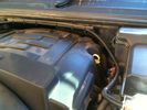
4GA Power Cable16 viewsFrom fuse box on aux battery - along channel.
|
|
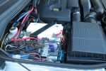
953 viewsAuxillary battery installation
|
|

faults 06/2-1416 viewsauxiliary belt tensioner
|
|
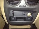
AUX Panel58 views
|
|

AUX Panel plug59 views
|
|

AUX panel plug58 views
|
|

Rosen DVD69 viewsMy overhead rosen dvd player with sony playstation 2 into aux.
|
|
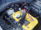
aux battery bracket41 views
|
|
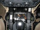
Here\'s a view of the Drive+Play "brain" which I mounted in the empty space in front of the gear selector.650 viewsI ran the power and audio cables to the rear of the center console in order to tap into the 12 volt power and "Aux" adapter. When you're sitting in the back seat, you don't see any cables whatsoever. My entire goal was to make it look as factory original as possible.
|
|
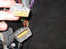
33 viewsConnector in LHS footwell, which connects (amongst other things) to the AUX input on the back of the stereo.
|
|
96 views
|
|

Interstate Battery Dimension sheet641 viewsThis sheet is hard to find - the sheet is not on the Interstate corporate web site but some dealer web sites display it. The pdf shows most of their available batteries including the H7 and H8 sizes that are the LR North America replacement batteries for the main starting battery. These batteries are of the Land Rover desired "shallow" cycle high discharge current Maintenance Free, (Ca Ca), internal construction, (not AGM, but instead, Wet Flooded Lead Acid with battery "caps" and Ca grid separators).
For the AUX battery , the H6, (BCI Group 48), is probably similar in dimensions to the Varta E12V75N that is popular in Australia. For that battery to fit in the second battery compartment, you must grind out the angled nibs on the inside front bottom of the LR black plastic surround, something I did wish to do and hence installed a Group 40R on a spacer. Alternately, one can choose an Interstate BCI Group 47 which is similar to a DIN H5 for the AUX location. I did this when I had to replace my 40R. No vertical spacer is required and the stock battery tie down bolts and clamp work well.
|
|
LR Stock 12v Outlet40 views
|
|
View from front left side looking towards rear aux battery compartment under cover 647 viewsAs there is no Fuel Burning Heater in the NAS V8 petrol vehicles, there is space available to install the FASKIT panel here. The piping is such that each air spring can be isolated from the air system and then filled one at a time manually via the Schrader valve. There are five Schrader valves and five shutoff valves. The fifth valve nearest the gauge controls air from the compressor, and can provide fill up air via a jumper fill line assuming the compressor is still operational.
|
|
Thread upload43 viewsImage uploaded in thread 47507
|
|

AUX power in rear of Disco103 viewsUsing hella aux power socket & cool magcode power port, also from hella,
|
|
Main Battery showing aux cable feed running off positive battery post.776 viewsThe black wiring loom around the battery cable to the aux battery was a part provided with the Traxide kit. My goal was to run the cable low enough such that the battery box cover would go back on as previous.
Note the hole drilled in the side of the battery box such that the new cable could thread thru to allow the battery box top to still fit the same as prior to the addition of the cable to the auxiliary battery.
|
|

Thread upload15 viewsImage uploaded in new thread
|
|
48 views
|
|
95 views
|
|

53 views
|
|
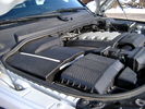
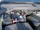
Overview of engine compartment from Main Battery side, (Passenger, LHD), looking across to Aux Battery753 viewsNote labels on main battery cover. The one you cannot read says that an auxiliary battery is installed on the other side. This is to warn service people should they wish to shut off all battery power.
The main starting battery is supposed to be of CaCa separator construction and DIN H8 or BCI Group 49 size. This means Calcium separators Wet Flooded Lead Acid, 13.9" long, 7.5" high and 6.9" wide.
On the Aux battery cover is a label saying to disconnect the blue Anderson single pole connector located under the cover by the brake reservoir. BCI Group 40R battery is small enough that the cover goes back on.
|
|
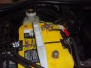
Re-wiring of 2nd aux battery130 views
|
|
12 Volt supply from aux battery82 views
|
|
12 Volt supply from aux battery86 views
|
|

Both connectors wired to aux battery90 views
|
|
permenant aux sockets ..place link wire here 158 views
|
|
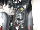
286 viewsPicture of the floor console removed. The wiring moving along from the bottom of the picture forward is power from the rear power socket, and audio from the aux port.
|
|
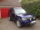
D4 with ProSpeed Rack, RAI, Winch, Auxillary Hella HIDs and Lamp Guards350 views
|
|
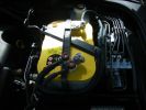
396 viewsThe OPTIMA aux battery
|
|
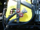
340 viewsConnection on the aux battey- Starter cable and supply wire
|
|
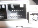
12 pin Aux socket on rear of Hi Line Stereo11 views
|
|
Hi Line stereo plugs with radio removed. Aux plug on the left14 views
|
|
372 views
|
|

Thread upload5 viewsImage uploaded in thread 185378
|
|
Aux Battery Installed1032 viewsIts a tight fit, but uses the LR battery mounts and bracket, slightly modified.
|
|
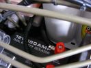
12v Isolator876 viewsEnsures that aux ery won\'t charge until the main batt is topped up and won\'t drain the main batt. I used the biggest I could find to take the load with no stress - especially the higher voltage on the landy. Came as a compete kit and works well.
|
|
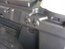
2 new rear 12v outlets933 viewsI added these two after market 12v oulets that are directly wired via a 30amp fuse to the aux battery. Why 2? Well you can never have enuff in my experieince... There\'s also a 12v socket wired to the ignition on the other side.
|
|

Thread upload1 viewsImage uploaded in thread 200210
|
|

Thread upload2 viewsImage uploaded in thread 200210
|
|
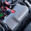
Thread upload4 viewsImage uploaded in thread 200210
|
|
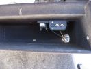
1337 views
|
|
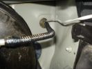
120 viewsThe signal wire then drops into the aux battery box and through the bulkhead grommet
|
|
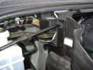
Signal wire through aux battery box to grommett124 views
|
|

Tasto Aux21 views
|
|
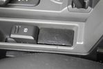
Little speaker to get nav instructions while listening to the radio133 viewsThe sound of the PDA is routed to the Aux input of the car. this way MP3 music and Nav instructions get to the car\'s audio system. But when you want to listen to the radio and also hear nav instructions, you can\'t hear them both through the car radio. For that I mounted a little speaker.
|
|
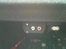
USB/AUX audio in61 views
|
|

Varta Battery Dimension chart570 viewsThis pdf provides Varta dimensions for among others, the E12V75N, (old DIN H6 or 85605 or BCI Group 48 size). This appears to be a deep cycle battery and the choice for many re the Aux battery install as long as you are willing to grind away the angled nibs at the bottom front of the battery surround. My choice was a shallow cycle battery intended for cold weather related engine starting rather than winch use.
Note the pdf Varta batteries are all deep cycle batteries suitable for running fridges, winches etc, rather than for engine starting and hence a good Aux battery if those are the intended uses rather than engine starting.
Varta now makes a Varta G14 with AGM technology and known as a Stop Start Plus battery. It is 95Ah, CCA of 850A; length 353mm; Width 175mm; Height 790mm and is specific for these newer stop start vehicles such as some D4's. For the 3's, one is still probably better off with an H8 sized battery but of the older Wet Flooded Lead Acid type and battery caps rather than a sealed AGM.
The Land Rover part number for the recommended battery is LR033179.
|
|

Thread upload6 viewsImage uploaded in new thread
|
|
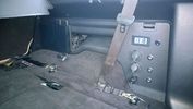
PS2 + Split charge system 10 viewsPS2 - Wireless controllers and headphones.
Split charge system with auxiliary sockets with digital voltage display
|
|
rear aux input prior to mod28 viewsrear aux input prior to mod
|
|
|
|