| Search results - "cable" |
17m cable6 views
|
|

personalised most cable 195 views
|
|
RRS MOST Cable65 views
|
|
FFRR MOST Cable59 views
|
|
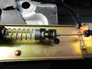
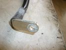
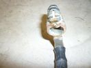
Cavo nel morsetto - Cable in clamp47 viewsHo inserito il terminale rotto nel morsetto: bisogna sforzarlo molto e ho praticato una cava attraverso il foro della vite con una punta in modo che il terminale non possa scivolare.
I entered the terminal broke into the clamp: you have to force it a lot, and I practiced a quarry through the screw hole with a bit so that the terminal can not slip.
|
|
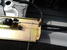
In caso di emergenza - For emergency48 viewsNel caso dovesse succedere nuovamente ho predisposto un cavetto da tirare.
If it were to happen again I have set up a cable to pull.
|
|

Attuatore rimontato - Actuator reassembled40 viewsAttuatore rimontato col cavo di emergenza.
Actuator riassemble with emergency cable.
|
|

234 viewsThe cable loom for the lights (installed by 10forcash)
|
|

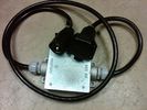
194 viewsCable loom with connector
|
|
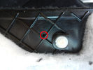
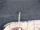
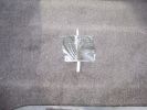
Foro pannello - Panel hole40 viewsHo forato il pannello moquettato per far passare il cavo di emergenza.
I drilled the carpeted panel to drive the emergency cable.
|
|

11 views
|
|
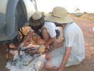
16 All the remains of a D3\'s parking brake371 viewsAfter 4 hours of hammering, finally removed the disk/park brake drum, and nearly all the parking brake bits fell to the ground. Cut rhe remaining brake cable loose as it was wrapped around the hub and a bit melted. Also having 2 jacks + 2 jack stands will support 4 hrs of hammering on the side of my D3.
|
|
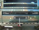
Cable wound in and hooked to recovery point958 views
|
|
![Filename=2009_05_06_10_04_41_dock%20cable[1].png
Filesize=33KB
Dimensions=234x199
Date added=05.Dec 2009 2009_05_06_10_04_41_dock%20cable[1].png](albums/userpics/14951/thumb_2009_05_06_10_04_41_dock%2520cable%5B1%5D.png)
71 views
|
|
102 viewsEarth stud with earth cables attached
|
|
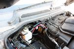
114 viewsBattery to battery cable in place along edge of engine bay
|
|
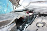
120 viewsModified aux battery box cover with shape of battery to battery cable. I also removed the tab which was fouling my traxide brain mounting bolts.
|
|
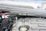
97 viewsBattery to battery cable tied to edge
|
|
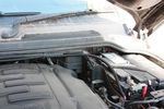
107 viewsBattery to battery cable in main battery box
|
|
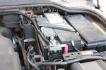
113 viewsBattery to battery cable attached to main battery
|
|
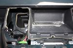
85 viewsDrilling a hole in the rear part of the floor of the dash pocket for the cables to go through
|
|
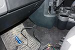
88 viewsCables out into passenger footwell
|
|
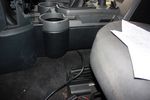
92 viewsStuffing cable under the floor console
|
|

63 viewsCables grouped together and routed neatly. Cable sleeving can be seen cable tied to the VGA screen cables at this point
|
|
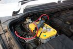
130 viewsBattery clamped down, terminals and cables attached
|
|
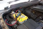
130 viewsAll done. Added some cable sleeving to avoid cables rubbing against battery clamp
|
|
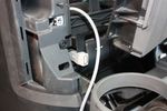
69 viewsUSB socket finally wedged in place. Cable routing will take the same route as VGA screen cables
|
|

most loop out cable 80 views
|
|
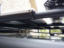
solar panel install347 viewsAt least at this point, I mounted it by using Clear Silicone RTV. This stuff is kind of like glue, but can be removed. If it doesn't hold up after curing and driving, I'll remove it and come up with another plan. I used heavy cable ties on the 4 grommets, in case it lets loose, it won't take out my wiring and the car behind me. 2 Panels are dandy like this, but I don't want to permanently block the roof space. Grape Solar to power my snomaster fridge
|
|
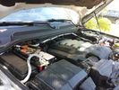
Traxide USI-160 Install493 viewsOverview picture of Traxide USI-160 upgrade install. This was an upgrade from the SC80 which performed flawlessly. The USI-160 had two relays and can deliver more amperage. As a result, the wiring was upgraded to 4/0 Welding Cable (warn) and heat shielding was added. The unit performs flawlessly to support 2 HAM Radios, Fridge, etc. Like me https://www.facebook.com/DifferentialPartsUS
|
|
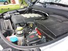
Winch Power upgrade306 viewsUsing 2 warn kits, and removing one of the wires to use on another project. The purpose was to replace the power and ground wire. I used Warn kits, which are 4/0 Welding cable. The original red #4 warped from getting a little too worn. The 2nd
Battery #1 Deka 9A94 AGM Intimidator, Battery #2 Deka 9A47 AGM Intimidator WARN 36080 28" Quick Connect Cable X 2, WARN 26405 Quick Connect Cable 7' X 2, WARN 15901 Black Cable X 1 -- winch control 72" X 1 https://www.facebook.com/DifferentialPartsUS
|
|

Brake shoe arm 17 viewsCable retaining spring location
|
|

Brake shoe arm20 viewsCable retaining spring location 2
|
|
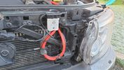
Thread upload2 viewsImage uploaded in new thread
|
|
Thread upload2 viewsImage uploaded in new thread
|
|
Thread upload2 viewsImage uploaded in new thread
|
|
Thread upload2 viewsImage uploaded in new thread
|
|
Thread upload2 viewsImage uploaded in thread 99648
|
|
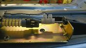
Thread upload1 viewsImage uploaded in thread 99648
|
|

Pearl Lugger - Cable Beach81 views
|
|
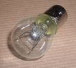
Land Rover Stop Tail Light dual filament bulb nominal 12 volt 21 / 5 watt filaments1412 viewsThis is the Land Rover part number 264590 dual filament bulb, (P21/5), that inserts into the upper two tail lamp receptacles. In the upper one, both filaments function, in the lower one, only the 5 watt tail light filament functions.
I regard it as not a good practice to routinely switch bulbs when the tail light filament, (5 watt), burns out on the lower bulb. The broken filament can jiggle over onto the brake light filament, (21 watt), and short the circuit to ground or something else not predicable.
There are also arguments to say that quality control is better on the Land Rover marketed bulbs than say far east sourced bulbs. Filament construction, and hence resistance can vary and mislead the current sensing circuits monitoring the signal light systems. Also when the bulbs are properly installed, all filaments should be standing vertically and not at any slope.
These are the sort of obscure circumstances that can lead to false trouble messages on the display, dropping to the stops, and subsequent concerns - all over a tail/signal light bulb.
For example, the filament life of both the tail light and the brake light filaments in the P21/5 bulb is significantly less than the USA common 1157 dual filament bulb, (1000/250 vs 5000/1200 hours); brightness in the P21/5 is a bit more, (3cp/35cp vs 3cp/32cp where cp is candle power), but current consumption is oddly less, (0.44a/1.86a vs 0.59a/2.10a where a is amps). It is the quest for efficiency vs maintenance trade off.
|
|
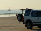
Cable Beach - Broome85 views
|
|

Cable Beach - Broome84 views
|
|

Cable Beach - Broome84 views
|
|
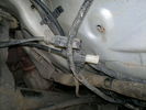
Left hand wheel sensors cable ends76 views
|
|
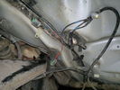
Front wheel sensor cables108 views
|
|
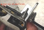
Bracket to hold emergency cable128 views
|
|
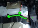
4 ICE Loom - routing of cable behind drivers seat58 views
|
|
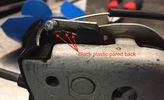
Close-up of lock showing emergency cable and pared back plastic tab138 views
|
|
Thread upload9 viewsImage uploaded in thread 135796
|
|

Fibre Optic MOST bus plus CAN, LIN, GVIF and SLIN buses1523 viewsThis 7 page pdf introduces the fibre optic MOST bus, (the orange coloured cables), the two high and medium speed CAN buses, the Gigabyte Video InterFace, Local IntercoNnect, and Security Local IntercoNnect buses.
|
|

Running Cable Through Rear - under seats126 views
|
|

10 views
|
|
6mm PA12 grade nylon tubing with heat shrink applied 539 viewsShows some of the 6mm air line with heat shrink applied to one end of tubing. Shrink will be applied to the other end once field cut to length. These four tubes, each about 20 ft (6m) long, feed to the rear. Re the front air lines, (not shown), four additional lengths, each about 10 ft (3m) long, are required plus one more 3 metre length for compressor air. The 6mm tubing is a Nylon product specified as PA12. There is also a very similar Transport grade PA11 material, however it seems that PA12 is the more common Transport grade now in use. Also the applicable DIN standard seems to be both DIN 73378 and DIN 74324 for the nylon tubing. The working pressure of the 6mm tubing is about 27 Bar and bursting 82 Bar @ 20C. This is for the 1mm nominal wall thickness material, (4mm ID, 6mm OD).
|
|
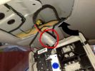
7 Voice / Telephone Mic Cable - pre fitted in roof70 views
|
|
1272 views
|
|

Thread upload1 viewsImage uploaded in new thread
|
|
Thread upload3 viewsImage uploaded in thread 193126
|
|
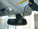
Cam mounted, cable tucked behind mirror (cool Disco3 sticker shot in the mirror)270 views
|
|
Cables being replaced19 views
|
|
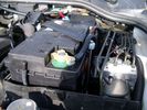
Aux Battery showing ground cable bolt "upside" down 1568 viewsIn order to obtain sufficient height clearance to get the plastic cover back on, I had to install the ground cable to the underside of the battery post connector.
Note the battery vent hose, (approx 5 ft required) is run down into where the windshield washer fluid container is located. There is not much electrical or metal in that area to be corroded by battery gas plus the open end of the vent hose tends to be protected from dirt and stays clean as well.
|
|
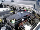
BCI Group 40R Deka 640RMF battery showing vent hose run forward to windshield washer reservoir area 1424 viewsRecessed post "Euro profile" battery to "match" OEM and stock Land Rover bracket; note that the Traxide SC80-LR module is mounted at an angle to allow for the main cable to sit under the cover so cover still closes.
The battery is a nominal 7", (180mm), high, but sits on a 1" battery spacer set under to raise the bottom front end of the battery such that the approx 11", (290 mm), length of the BCI 40R battery rises above the angled plastic nibs at the forward end bottom of the case front; hence sufficient space, (1/4", 5mm) remains at the brake reservoir end.
Also the 40R battery does not have hold down "flanges" on each end; on the sides yes, but not the ends so no additional length is required.
When I had to replace the 40R, this time I installed the shorter, (9.625"), taller, (7.5") Interstate BCI 47 / DIN H5 battery which eliminated the spacer on the bottom and better fit the stock LR tie down bolt lengths. Deka also has a BCI 47 / DIN H5 that would work fine as well.
|
|
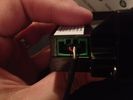
Aux Input Wiring Harness69 viewsUsed a modified PC CD interface cable to connect to stock female harness. Pins 3(R), 4(L), 5(G)
|
|

battery mounting and cables50 views
|
|
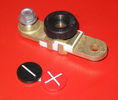
Battery Disconnect side post with + & - caps, top view616 viewsThis disconnect is designed for side post batteries. It can be used on either the + or - terminals. It can also be installed at the "other" end of the battery cable as well. In my install of the Aux battery, I installed this on the negative ground cable where the cable attaches to the body sheet metal. I have never used it but it seemed like a good idea at the time. The main battery hookup is pure stock.
For the hot side of the Aux battery, an Anderson PowerPole was used inline for the cable between the Aux and connecting to the spare bolt hole at the + post of the Main battery cable.
|
|
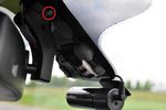
Fit cable to Blackvue77 views
|
|
Wrapped cable81 views
|
|
Fuse with cable71 views
|
|
Box Closed with 7 Blade NAS connectors578 viewsBox closed up and ready for use. The box and cable connectors are reasonably weather tight and hence can be submerged for a bit while doing a creek crossing but as with the 3, do not use the creek bed as a parking stall. Similarly, the connector recessed into the bumper will probably remain somewhat dry as long as you keep moving but if you get stopped, well that is another story.
As such, I put a vial of desiccant in the metal box prior to closing it up to reduce corrosion due to moisture build up.
|
|
brake sensor cable5 views
|
|
Smooth Talker Amplifier Box mounted below near steering column.179 viewsThe gold look box due to the lighting, (actually black), is the antenna amplifier located near the steering column. It can be put anyway but this seemed an OK location as I ran the antenna connector cable rearward from here to the back corner of the 3 and then up to the underside of the roof glass at the rear. The blue/white thing is the brake light switch that often must be replaced. See the Brake Light Switch file within this Gallery regarding the switch replacement.
|
|

Grommit20 viewsOn manual D3's this is used by the clutch. Om Autos it may be free for routing a cable
|
|

85 views
|
|
Cable loom cover403 viewsHow do you remove it???
|
|
LH cable tucked under ribbed bumper plate160 views
|
|
Detector Cable left158 views
|
|
Cables out from bottom LH corner of LHS cubby hole160 views
|
|
RH cable tucked under ribbed bumper plate163 views
|
|
158 views
|
|

503 views
|
|
Power pickup from white towbar skt153 views
|
|

Thread upload13 viewsImage uploaded in thread 22757
|
|

10 views
|
|
Thread upload10 viewsImage uploaded in thread 160019
|
|

Thread upload5 viewsImage uploaded in thread 181080
|
|

Thread upload0 viewsImage uploaded in new thread
|
|

Thread upload10 viewsImage uploaded in new thread
|
|
2m cable5 views
|
|
43 views
|
|

Thread upload0 viewsImage uploaded in new thread
|
|
Power pickup from white towbar skt153 views
|
|

Thread upload9 viewsImage uploaded in new thread
|
|

52 views
|
|

Thread upload8 viewsImage uploaded in new thread
|
|

Thread upload10 viewsImage uploaded in new thread
|
|

Thread upload0 viewsImage uploaded in new thread
|
|

Thread upload9 viewsImage uploaded in new thread
|
|
49 views
|
|

Thread upload0 viewsImage uploaded in new thread
|
|

Thread upload10 viewsImage uploaded in new thread
|
|
Rear passenger (left) wire harness channel41 views
|
|

Thread upload10 viewsImage uploaded in new thread
|
|

45 views
|
|

48 views
|
|
43 views
|
|
Tidied & ready to go56 views
|
|
9 views
|
|

Thread upload0 viewsImage uploaded in new thread
|
|

Thread upload28 viewsImage uploaded in thread 92518
|
|

Thread upload22 viewsImage uploaded in thread 92518
|
|

Thread upload26 viewsImage uploaded in thread 92518
|
|

Thread upload0 viewsImage uploaded in new thread
|
|
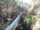
30 viewscable car up...tabogin down..fun
|
|
Thread upload16 viewsImage uploaded in thread 87553
|
|

Thread upload8 viewsImage uploaded in thread 99648
|
|
Thread upload4 viewsImage uploaded in thread 150447
|
|
Thread upload2 viewsImage uploaded in thread 150447
|
|
Thread upload3 viewsImage uploaded in thread 150447
|
|
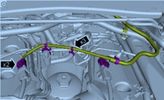
Thread upload3 viewsImage uploaded in thread 123654
|
|
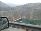
nice cable stay bridge..unused30 views
|
|

Thread upload20 viewsImage uploaded in new thread
|
|

Changing a Lower Tailgate Stay Cable.pdf8 views
|
|

Thread upload4 viewsImage uploaded in new thread
|
|

Cam cable to upper tailgate27 views
|
|
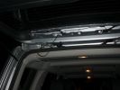
Cable Routing through top of tailgate49 views
|
|

1227 views
|
|
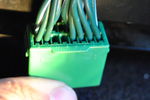
Speaker cables66 views
|
|

D4 Cubby Cooler iPod Cable slot65 views
|
|

Thread upload19 viewsImage uploaded in thread 184914
|
|

Thread upload23 viewsImage uploaded in thread 184914
|
|
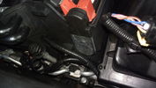
Cable routed from secondary battery box to front grille110 views
|
|
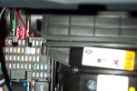
Tapa-circuit383 viewsTapa-circuit fitted to fuse box behind glove box. Red cable to top is the fused output cable leading to the PDA charger
|
|
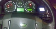
ipod detail159 viewsipod mounted without lr´s ipod kit. A cable cames from HK back aux input.
|
|
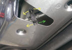
Thread upload11 viewsImage uploaded in thread 33743
|
|

Thread upload4 viewsImage uploaded in thread 150447
|
|
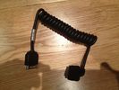
ipod cable44 views
|
|
634 views
|
|
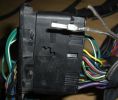
New Speaker Cables.107 viewsThis is the door connector, Main loom to Right, Door side to the left. to the top of the connectors you can see green and Green white wires which are the speaker ones. The door wiring is premium and has two pairs, the main loom was a 1 pair high line, so i am adding the pair you see (one already pinned up) to upgrade the loom to premium.
|
|
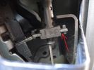
Thread upload17 viewsImage uploaded in thread 170806
|
|

Thread upload18 viewsImage uploaded in thread 170806
|
|

winch cable cover140 views
|
|

Lead Car Entering the Finish115 views7 May 2007 - My D3 on duty as lead car in shinfield 10K road race. what a nightmare driving at low speed in the rain. Clock was mounted on standard crossbars. connection to additional batteries in boot cable thru side window. There is a small offroad section (actually an un-made road) Oaklands Road, Shinfield, Reading (suggest anyone test driving in the Reading area take this road)
|
|
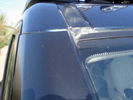
139 viewsCable routing for roofrack
|
|
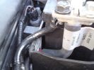
Take power direct from battery, routed cable through some rubber pipe, then taped up166 views
|
|
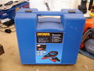
Halfords Booster Cables33 views
|
|
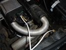
W-Bus out cable in pin 2 (NOT the same cable going to ground!!!)75 views
|
|
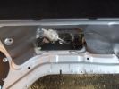
An alternative approach130 viewsDue to low temperature, and the size/mobility of my hands I decided that the easiest way to open the tail gate was to destroy the old Bowden cable and then pull centre core to release the tailgate - it worked, and doing this earlier would have saved a few cuts and grazes.
|
|
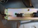
The old, broken one119 viewsNote the gap between the end of the Bowden cable and the place its meant to be....
|
|
Shiny new cable113 viewsConnected to the solenoid, and looking quite smart. I hope this will last longer than the old one.
|
|
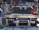
Installed winch with electrical solenoid connections158 viewsI routed the electrical supply (2 small wires) up the side of the radiator. You can see the unconnected wires inside the red boxes. I ended up connecting them on the radiator diagonal strut with cable ties. They are out of the way for any deep water transits there.
|
|
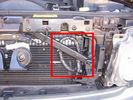
Installed winch electrical wires146 viewsWires which only power the solenoid are inside spiral wrap. They are also connected inside the wrap at the high point of the loop. Cable tied into place to prevent vibration rubbing.
|
|
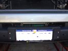
Winch as installed176 viewsLicence plate is held on by winch cable and 4 metal pins which fit into modified bumper body. Winch rope is green
|
|
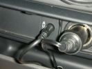
498 viewsRear iPod cabling solution. Notice the hole where the cables descend into the rear of the center console.
|
|

106 viewsPower cables passed through grommet
|
|
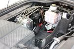
117 viewsCircuit breaker at other end of power cable
|
|

Thread upload26 viewsImage uploaded in new thread
|
|

Thread upload1 viewsImage uploaded in new thread
|
|
32 views
|
|

Thread upload1 viewsImage uploaded in new thread
|
|
Thread upload24 viewsImage uploaded in thread 109204
|
|

Thread upload21 viewsImage uploaded in thread 109204
|
|
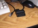
Scan Gauge ODB Cable93 views
|
|
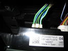
cable onto controller103 views
|
|

...male-female converter used for testing (will get a proper female cable once checked)...94 views
|
|
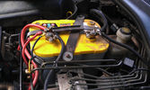
The auxiliary battery21 viewsThe auxiliary battery in the bay.
As the wiring diagram I made shows, there's a wire leading to the fuse box in the rear. (is going through the key-switch)
The second one is going to the fog lights. The smaller cables which should be connected to the head-lights, are connected to the battery.
The third one is going to the compressor (via a switch) (sits before the key-switch)
A fourth one is going to the CB and battery check display (sits before the key-switch)
|
|

12V to dual USB10 viewsAs the USB cables were running to the booth, I added a 12V to dual USB charger in the booth and connected the USB cables.
|
|

Emergency tailgate opener35 viewsDrilled a little hole for the string tied to the talgate cable.
|
|
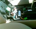
621 viewsEmergency hand brake cable (loop)
|
|
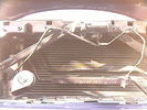
Front Horn and extra cable and socket234 views
|
|

Tailage cable fix22 viewsThe broken cable elbow is fixed to the motor with two pieces of steel wire. I've also tied a string so I can open if the motor dies.
|
|

Thread upload4 viewsTowbar Electrics - Cable Route
|
|
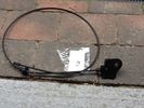
Bonnet cable22 views
|
|
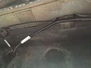
Thread upload3 viewsTowbar Electrics - Cable Route
|
|
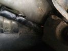
Thread upload4 viewsTowbar Electrics - Cable Route
|
|

Thread upload4 viewsTowbar Electrics - Cable Route
|
|

Thread upload3 viewsTowbar Electrics - Cable Route
|
|
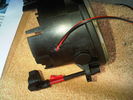
Hole Drilled/Cable Pulled Through118 views
|
|

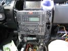
2035 viewsEverything pulled to bit\'s in order to get cables in for PC Screen etc.
Note the panel with USB and LAN connectors on, this replaces the LR panel with the ash tray in.
|
|

Aux Battery917 viewsShopwing the addition of the 35mm2 cable going to the split charge relay
|
|
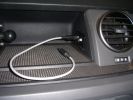
Connectors for Sound out and DC in178 viewsSound out (cable inserted) - connected to Aux connector in passenger footwell.DC in connector is always live
|
|
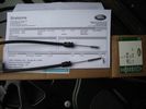
Broken cable end and new item21 views
|
|
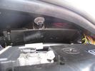
Cable holder by battery192 views
|
|
top side of chapel in le frith at 4pm today84 viewsthis is what my discovery is built for to tow a 3.5ton generator and carry 900KG of cable to keep the power on for the people of hope village in the peak district
|
|
ipod cable189 views
|
|
Dension Gateway 500 MOST Cable64 views
|
|
4GA Power Cable14 viewsFrom fuse box on aux battery - along channel.
|
|
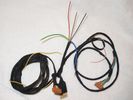
cable harness63 views
|
|
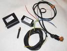
LR3 Bundle & cable harness70 views
|
|
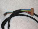
GSM box end of the cable harness75 viewsGreen, blue & orange wires not connected
|
|
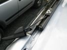
Alternative aerial cable route72 views
|
|
Alternative aerial cable route68 views
|
|
Alternative aerial cable route78 views
|
|
Alternative aerial cable route83 views
|
|

Alternative aerial cable route81 views
|
|

Alternative aerial cable route77 views
|
|
Alternative aerial cable route73 views
|
|
Alternative aerial cable route81 views
|
|

Alternative aerial cable route76 views
|
|

Alternative aerial cable route84 views
|
|

Matt Black Porsche seen in Vienna41 viewsnote the body kit and the paint but the best bit is the cable tie keeping the number plate on.
|
|

Routing of cable46 views
|
|

Routing of cable45 views
|
|

Routing of cable45 views
|
|

Cable routing in engine bay28 views
|
|
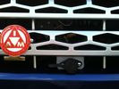
Cabled winch control connector112 viewsAdditional angle bracket made for connector in aluminium attached to red grill. Additional in-line connector between this and the solenoids to allow rad grill to be removed when required.
|
|
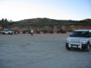
Camels and Disco 3 on Cable Beach Broome123 views
|
|
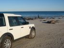
Cable Beach Broome, WA130 views7:00am Cable Beach
|
|

Sunset on Cable Beach, Broome, WA, Australia123 views
|
|
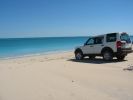
Northern end of Cable Beach, Broome, WA, Australia149 views
|
|

Cable Beach Broome, WA170 views
|
|
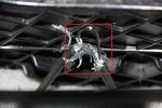
This is the cable I hacked trough with snips then tugged the core86 views
|
|
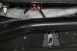
This is the cable in relation to the catch77 views
|
|

Towing socket battery charging cable38 views
|
|

Hand Brake Cable Hanger8 views
|
|
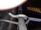
Hand Brake Cable Hanger6 views
|
|
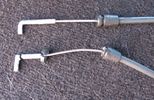
Reae tailgate cable - Old broken and a new one36 views
|
|
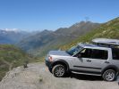
Col de la Tourmalet France 200952 viewsHolidays in France high up in the Pyrenees we decided to drive up to the top of the Pic du Midi at an altitude of 2877m instead of taking the £60-00 cable car. Just don\'t look down. What a Day!
|
|
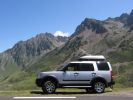
221 viewsHolidays in France high up in the Pyrenees we decided to drive up to the top of the Pic du Midi at an altitude of 2877m instead of taking the £60-00 cable car. Just don\'t look down. What a Day!
|
|
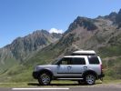
58 viewsHolidays in France high up in the Pyrenees we decided to drive up to the top of the Pic du Midi at an altitude of 2877m instead of taking the £60-00 cable car. Just don\'t look down. What a Day!
|
|
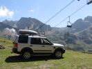
Why take the lift when you have a Landrover49 viewsHolidays in France high up in the Pyrenees we decided to drive up to the top of the Pic du Midi at an altitude of 2877m instead of taking the £60-00 cable car. Just don't look down. What a Day!
|
|
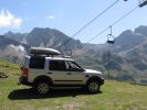
Why take the lift when you have a Landrover232 viewsHolidays in France high up in the Pyrenees we decided to drive up to the top of the Pic du Midi at an altitude of 2877m instead of taking the £60-00 cable car. Just don\'t look down. What a Day!
|
|
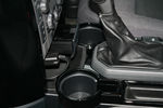
58 viewsCharger for tom tom, cable running behind H trim
|
|
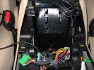
This is the hole that I drilled to get the iPod cable into the center storage area.466 viewsThe hole needed to be this large as both ends of the cable are large.
|
|
Here\'s a view of the Drive+Play "brain" which I mounted in the empty space in front of the gear selector.649 viewsI ran the power and audio cables to the rear of the center console in order to tap into the 12 volt power and "Aux" adapter. When you're sitting in the back seat, you don't see any cables whatsoever. My entire goal was to make it look as factory original as possible.
|
|

This is where my iPod will live, unless I need to take it out to add songs or update playlists.491 viewsI installed a rubber grommit between the cable and the hole to keep it from rubbing on the sharp plastic.
|
|
LED light - fixing bolt and cable size79 views
|
|

LED light - cable through boot into upper tailgate104 views
|
|
View of tailgate actuator with cable going into it93 views
|
|
Cable must be removed first9 views
|
|

Thread upload21 viewsImage uploaded in thread 92518
|
|
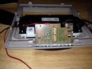
Thread upload21 viewsImage uploaded in thread 92518
|
|
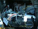
136 viewsA Class Hands free phone install HCB-700
|
|

InteriorReleaseCable22 views
|
|
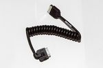
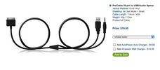
Genuine Discovery4 I-Pod Link Lead (LR031492)51 viewsGenuine Discovery4 I-Pod Link Lead (LR031492)
|
|

Thread upload0 viewsImage uploaded in new thread
|
|

Thread upload0 viewsImage uploaded in new thread
|
|
Thread upload7 viewsImage uploaded in thread 91468
|
|
Thread upload6 viewsImage uploaded in thread 91468
|
|
Thread upload6 viewsImage uploaded in thread 91468
|
|
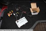
Everything thats included77 viewsCamera & GVIF and all cables after removal
|
|
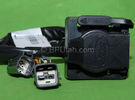
Harness section that runs behind the rear bumper.405 viewsThis is the harness section that clips up inside the rear bumper and includes the circular 7 pin, (6 flat +1 round), NAS socket, and also the 4 pin NAS flat connector.
The two small plug ends connect under the rear left tail light to the harness section that exits from the interior.
The Land Rover part number for the NAS trailer tow kit, (both cables), is YWJ500220.
|
|
Here it is attached to the caravan "A" frame.631 viewsThe cable ties are temporary until I can drill and tap a couple of holes for screws.
|
|

Upper tailgate lock / cable30 views
|
|

Loose cable14 views
|
|
52 views
|
|
Dust Seal duct taped back together 2259 viewsThis shows the dust seal duct taped back together; also the surplus wire rope exiting from the actuator area prior to being cut to length.
I do not think the sticky plastic membrane is a dust seal, but more of a cable protector to cover up the wiring bundle that is effectively sticking to the underside of the flexible membrane.
|
|
Flexible wire rope fishing leader 0.032" diameter exiting carpet 1932 viewsThis is all you see of the completed mod.
The short little angled "line" about an inch long that looks like a piece of debris and is located a few inches "above" the support cable is actually the wire rope release cable exiting from under the carpeted lift gate cover.
I drilled a very small hole in the carpet and pushed the 0.032" diameter release wire thru and then slipped the loose end under the black plastic.
To release with the lift gate etc closed, from the inside, just pull the loose end free from under the black plastic and gently pull wire about 5mm, (1/4"), and the upper door catch should release. You will have to manually push the upper door out wards to actually effect opening, but you will already be inside the rear cargo area so that part is easy to do.
The assumption is that the lower door latch still works electrically and hence, the lower lift gate half will open as normal by pressing the usual button on the top left of the lower door half.
|
|
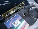
0.032" OD metal fishing leader and lead fishing weight clamped to existing wire rope 2105 viewsI used a size #0 lead fishing weight as a clamp to attach the 0.032" diameter flexible wire rope fishing leader to the release cable.
The pictured weight is the smaller #00 weight, however it did not work very well so reinstalled with the larger #0 size. I clamped to the cable as what breaks is the L retainer that is hidden in the actuator and holds the cable. When the L breaks, it lets go of the cable so you hear the clicking but there is no opening action.
Clamping on to the cable is an attempt to resolve that reality; also if the actuator electrically fails, the release mod should still do the task. Note in the picture the two Torx T15 screws that hold the gold plate to the plastic case and also the two 8mm cap screws that have to be loosened to remove the actuator from inside the door.
|
|
![Filename=LR3_Radio_Removal[1].pdf
Filesize=190KB
Dimensions=320x240
Date added=04.Feb 2014 LR3_Radio_Removal[1].pdf](images/thumb_pdf.jpg)
Radio Removal from Radio Stack567 viewsThis shows how to remove the radio from the stack. Basically you remove the H surround first and then at least loosen all the Torx 20 screws left and right sides from the top down starting at the narrow unit that the four way flasher/locking buttons are mounted on.
The units kind of interlock, hence some movement of each is required to remove the radio by itself. I find it best to take out the four way flasher/locking buttons assembly first as that allows access to the fibre optic cable connector into the back of the radio head without too much tugging.
|
|

Rosen A10 Land Rover Installation Manual831 viewsThis is a 11 page pdf which is the Land Rover version of the A10 installation manual for our 3. It consists of a hundred plus sketches showing how and where to connect various cables, conductors and plugs.
|
|

LTB00145 - Technical Bulletin - Remove & Install Parking Brake Cables89 views
|
|

LTB00314 - Technical Bulletin - Seat Motor Drive Cable Availability66 views
|
|
Thread upload1 viewsImage uploaded in new thread
|
|
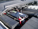
Main starting battery showing 1/2" hole drilled for power cable egress905 viewsView of OEM battery in Left Hand Drive LR3. This is supposed to be a Battery Group BCI 49 or H8 sized battery but in reality is the slightly shorter BCI 94R or H7 battery that fits easier lengthwise, (12 3/8" vs 14").
Note the 10mm hole drilled in plastic of surround to allow for entry of main power cable that runs between batteries. The cable bolts to a spare 6mm threaded hole in the OEM battery cable end; the light gauge wire runs to the front of vehicle to a connector for the CTEK MULTI US 3300 charger. Coloured felts, (red and green), are a material treated to reduce battery post corrosion. The OEM battery ground cable is only about a foot long and runs to an 8mm stud located on the inner fender just to the rear of the fuse case.
|
|
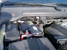
Main Battery showing aux cable feed running off positive battery post.771 viewsThe black wiring loom around the battery cable to the aux battery was a part provided with the Traxide kit. My goal was to run the cable low enough such that the battery box cover would go back on as previous.
Note the hole drilled in the side of the battery box such that the new cable could thread thru to allow the battery box top to still fit the same as prior to the addition of the cable to the auxiliary battery.
|
|
Thread upload54 viewsImage uploaded in thread 52879
|
|

64 viewsThe cover that you remove to access the cable, for manual release of the electronic parking brake.
|
|

most cable fitting449 views
|
|

most cable layout254 views
|
|

Thread upload28 viewsImage uploaded in new thread
|
|
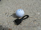
MOST fiber optic loop tool466 viewsThe looping tool in the jpg uses the Land Rover type plastic fiber optic cable with both ends feeding back into a female fiber optic connector that mates with the male fiber optic connectors on the Land Rover system.
The purpose of the loop is to allow one to disconnect MOST connected items such the BlueTooth module or the HK amplifier but allow the MOST system to still transmit signal from the head unit as the circuit would remain closed and hence complete. Of course with the Bluetooth module disconnected, there would be no Bluetooth available, however the radio and NAV would still function.
The looping tool allows one to troubleshoot the system by removing one component at at time from the MOST loop. In other words, what might appear to be a radio problem could be a Bluetooth problem - that sort of thing.
|
|
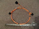
Fibre Optic MOST cable between components.557 viewsThis is a typical section of Plastic Optical Fiber (POF) optic cable with the orange coloured cladding covering the perimeter of the light transparent core. This is used as the MOST (Media Oriented Systems Transport) data transmission medium.
Note that each MOST 1355426 optical connector holds a pair of light conductor cables, one transmitting optical signal in, and the second, optical signal out. When connected to the other cables and devices, the cables form a continuous loop.
The light signal within the cable is red colour as one might expect. One break or disconnect anywhere along the loop shuts down signal transmission to all the connected components.
|
|
Thread upload14 viewsImage uploaded in new thread
|
|

How to cable factory BT module (including MOST bus connector)82 viewsInstructions to install Factory BT module in a Disco 3 that has LR aftermarket or no BT module installed
|
|
Tie-Wraps769 viewsWhen the EGR pipes are removed, you lose the brackets these cables are normally secured to because the brackets are part of the pipes. This is my solution to the problem - refit the bolts with an almost closed tie-wrap around them, then slip a new tie-wrap through the loop on that one and around the cable.
|
|
Thread upload2 viewsImage uploaded in new thread
|
|

Thread upload19 viewsImage uploaded in thread 92518
|
|

21 viewsConnectors for T91-Altox Y Cable
|
|

20 viewsConnectors for T91-Altox Y Cable
|
|

22 viewsConnectors for T91-Altox Y Cable
|
|

20 viewsConnectors for T91-Altox Y Cable
|
|
910 views
|
|
FL2 MOST cables68 views
|
|

Aerial cable run149 views
|
|

Aerial cable run145 views
|
|

Aerial cable run141 views
|
|
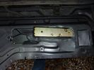
This contains the broken cable end85 views
|
|
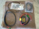
Traxide SC80-LR644 viewsKit -- cable was 6 feet short. Check to ensure the length is adequate prior to installing it.
|
|
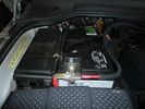
Traxide699 viewsLeft hand drive, primary battery with Traxide cable routed. The battery is on the right.
|
|
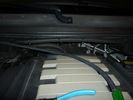
traxide cable run731 viewsTraxide cable between primary and secondary battery.
|
|
firewall plug run905 viewsHow to get the cable from the engine bay to the rear of the vehicle.
|
|
traxide797 viewsThis would be an ideal location for the traxide 80 kit, there are pre threaded holes available here.. would take a bit of fitting, and extending the cable to the primary battery would need to be extended.
|
|
rear socket install1022 viewsShows to white cable run, cable routing, cable ties and socket placement. Rear sockets fitted. Note the white power cable, and cable tie location. The socket in this position are neatly back out of the way, but handy.
|
|
Negative Battery Cable203 viewsThis shows the corrosion from the negative terminal on the Negative to body ground. This is likely due to gas released through the negative post. It appears to be a common problem with the LR3. As a result of this corrosion left unchecked will damage the computer ecu and cables mounted near and below the battery.
|
|
Negative Battery Cable151 viewsClose up of the corrosion damage to negative cable.
|
|
Negative Battery Cable158 viewsClose up of the corrosion damage to negative cable.
|
|

cable2125 views
|
|

cable1102 views
|
|
original MOST cable119 viewsreplace the short cable from Radio to Nav display with part of the additional MOST loom (YMQ502470)
|
|
additional most cable added to radio & nav display 109 views
|
|
end of the additional MOST cable76 views
|
|
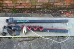
Maxxraxx35 viewsMaxxraxx fixed towball mounted bike rack. Top: upright with pivot and locking pin. Bottom left: towball mount with spacer and 50mm towball. Bottom right: horizontal member with three bike carriers, securing strap and security cable.
|
|
Traxide installation - rear cable19 views
|
|
Damaged OEM's held together with cable ties52 views
|
|
Damaged OEM's held together with cable ties49 views
|
|

Thread upload3 viewsImage uploaded in thread 150447
|
|

Thread upload3 viewsImage uploaded in thread 150447
|
|

Thread upload2 viewsImage uploaded in thread 150447
|
|

Thread upload3 viewsImage uploaded in thread 150447
|
|

d4 cables lose in boot38 views
|
|
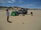
Cable beach80 views
|
|
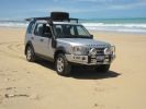
Cable Beach Broome88 views
|
|
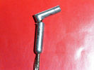
tailgate lock release cable 212 views
|
|
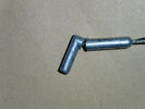
tailgate lock release cable21 views
|
|
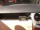
214 viewsTrailer Display unit when in use - Cable long enough to position anywhere suitable
|
|
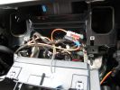
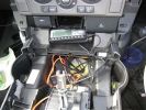
278 viewsClose up of the cavity for the Nav screen. Here you can see the XM Satellite receiver antenna cable snaking across. It\'s the thin wire not bundled to anything. In the lower corner you can also see the power cable going to the glove box.
|
|
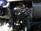
277 viewsA mess of cables. You can see the HD Radio antenna adapter coming out into the slot for the IHU. You can also see, if you look very closely, the original diversity antenna connector plugged into another adapter to go down to the HD radio unit.
|
|
254 viewsThe console mostly re-assembled. You can see the dremel notch I made for the control cables, as well as the slack in the power and audio cables.
|
|
329 viewsInstallation slowly proceeding. You can see the controller cables inserted into the notch I made with a dremel.
|
|
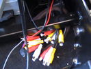
AV in and Output cables376 views
|
|
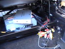
interface unit sat on dvd - cables pulled under seat frame408 views
|
|
12volt power from reverse light plus Video cable routed to from rear to under seat335 views
|
|
12volt power from reverse light plus Video cable routed to from rear to under seat319 views
|
|
12volt power from reverse light plus Video cable routed to from rear to under seat312 views
|
|
no need to remove this trim - cables easily go underneath them323 views
|
|
dead easy to get cables from boot to rear light cluster through existing grommets342 views
|
|
Thread upload15 viewsImage uploaded in new thread
|
|
337 viewsConnection on the aux battey- Starter cable and supply wire
|
|

Where is the 12V Cable17 views
|
|
RF Cable Route #1410 views
|
|
RF Cable Route #2362 views
|
|
RF Cable Route #3401 views
|
|
Thread upload4 viewsImage uploaded in thread 193079
|
|

Thread upload4 viewsImage uploaded in thread 193079
|
|
Wiring heated seat70 viewsThis picture is taking from behind the driver seat underneath.. the black cable that goes up in the hole is the wiring for the heat elements. There is a connector on the other end, not visible in this pic.
|
|
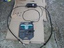
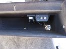
380 viewsOverview - box, two brake cables and release cable
|
|
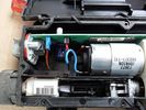
The lid is off!425 viewsShows motor, circuit board and left cable inner end
|
|
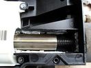
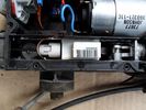
Now we are getting to it...439 views... the threaded (or DREADED) actuator - externally splined internally threaded element (centre of pic) rotated by gearbox (on left of pic) to pull cable end (externally threaded, on the right)
|
|
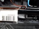
Strain gauge...391 views...I think.
On the left cable - with a latch (?function) and a ribbon connector cable
|
|
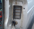
Release cable...361 views...passes round the pulley on the left...
|
|
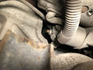
1334 views
|
|

Thread upload56 viewsImage uploaded in thread 31656
|
|
77 views
|
|

86 views
|
|
Thread upload0 viewsImage uploaded in thread 198799
|
|
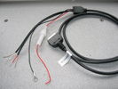
71 viewsplugs are cut off
|
|

Broken Tailgate Cable108 views
|
|
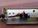
Thread upload8 viewsImage uploaded in thread 99648
|
|

PDF of the steps to add manual emergency tailgate release cable117 views
|
|
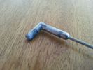
Thread upload56 viewsImage uploaded in new thread
|
|

Tekonsha Ford Brake Controller Adapter part number 3035-P270 viewsThis is the adapter cable between the Brake Controller and the existing C2590 female plug located near the brake pedal on NAS spec LR3's. The flat 4 pin plug of the adapter cable connects to the Controller; the rectangular 6 hole male plug to C2590.
There are only four conductors in the adapter cable, but one will see five pins within the Land Rover C2590 plug. The #2 pin is not required for the NAS setup. #2 pin is the circuit between the head lamp switch and vehicle side running lamps required in the civilized world.
The single pin at the bottom in the picture is #3 and on the Land Rover, a Black wire tied to ground. The other pin at the bottom and across to the left is #6, and Blue on the Land Rover. This is the Brake Controller output to the trailer socket at the rear.
#4 is the pin at the top left, and is a White coloured wire from the battery. Pin #5 is from the stop light switch, and is Green on the Land Rover.
Note that the adapter cable colours do not necessarily follow all the above referenced Land Rover colours.
|
|

Tekonsha P3 Brake Controller 90195 to Ford 3035-P wiring adapter plug306 viewsThis two page pdf is the general instruction for hooking up the Tekonsha part number 3035-P adapter cable between a Tekonsha P3 controller and the existing Land Rover/Ford plug, (called C2590 in the Land Rover wiring diagrams), that is hidden above the brake pedal.
The "Ford" plug, (C2590), is grey and is stuffed up above the brake pedal arm.
Mount the P3 controller appropriately and then connect one end of the custom cable to the P3 and the other to the "hidden" plug.
You will now have power for your trailer electric brakes in the round socket at the rear of your LR3; also no computer update from the Land Rover T4 unit is required. For once, it is plug and play.
If however, your trailer has LED tail lights, you may have trouble with the flashing of the trailer signal lights or non recognition by the 3 that a trailer is connected. As such, the little green trailer signal will not illuminate when a trailer is connected and the signal lights are used. This can affect the shifting of the transmission and much to your annoyance, the backup sensors will still be functioning rather than being auto disabled.
|
|

Tekonsha P3 Electric Trailer Brake Controller model 90195281 viewsOne model of electric brake controller that is commonly used on the LR3 is the Tekonsha P3 unit, model number 90195. It mates up to the LR3 with a custom "Ford" adapter cable, Tekonsha part number 3035P. No wire cutting or splicing is necessary - just mount unit and plug adapter cable in.
|
|
Thread upload27 viewsImage uploaded in thread 92518
|
|
EGR Actuator Cable868 viewsThe cable is tie-wrapped to the EGR pipe bracket so I had to cut the tie-wraps. The bracket is part of the pipe.
|
|
Thread upload14 viewsImage uploaded in new thread
|
|
Thread upload18 viewsImage uploaded in thread 108393
|
|
212 views
|
|
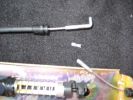
190 views
|
|
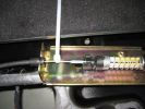
205 views
|
|
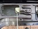
199 views
|
|
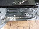
181 views
|
|
184 views
|
|
181 views
|
|
204 views
|
|
882 views
|
|
Amdeal 30ft / 10M USB Digital Microscope Cable Wire Endoscope Camera Video Recording Inspection Pipe Camera - Waterproof, 4 LED Lights23 viewsUnder XP system, can watch video directly without install software. By using our software, can take photo,record video, and save the video in the PC. Such USB microscope widely used to inspect tube, check the body, magnify stamps, coins, antiques, insects, electric circuits, machines, fabrics, food, decorations, etc. Please notice that the wire camera is designed for industrial use, not for medical use.
Camera: 1/6" VGA COMS
Pixel: VGA 300K
Resolution: 640x480,352X288,320X240,176X144,160X120
Capture Resolu
|
|

Thread upload10 viewsImage uploaded in new thread
|
|
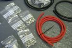
Take one box of cables and crimp fittings...101 views
|
|
|
|
|