| Search results - "cables" |
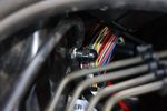
103 viewsEarth stud with earth cables attached
|
|
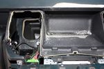
85 viewsDrilling a hole in the rear part of the floor of the dash pocket for the cables to go through
|
|
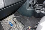
89 viewsCables out into passenger footwell
|
|

63 viewsCables grouped together and routed neatly. Cable sleeving can be seen cable tied to the VGA screen cables at this point
|
|
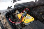
131 viewsBattery clamped down, terminals and cables attached
|
|
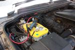
131 viewsAll done. Added some cable sleeving to avoid cables rubbing against battery clamp
|
|
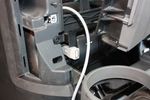
70 viewsUSB socket finally wedged in place. Cable routing will take the same route as VGA screen cables
|
|
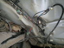
Front wheel sensor cables108 views
|
|

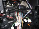
Fibre Optic MOST bus plus CAN, LIN, GVIF and SLIN buses1539 viewsThis 7 page pdf introduces the fibre optic MOST bus, (the orange coloured cables), the two high and medium speed CAN buses, the Gigabyte Video InterFace, Local IntercoNnect, and Security Local IntercoNnect buses.
|
|
1274 views
|
|
Cables being replaced23 views
|
|

battery mounting and cables50 views
|
|
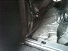
Cables out from bottom LH corner of LHS cubby hole164 views
|
|
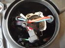
Tidied & ready to go60 views
|
|
11 views
|
|

Thread upload1 viewsImage uploaded in new thread
|
|

Thread upload30 viewsImage uploaded in thread 92518
|
|

Thread upload22 viewsImage uploaded in thread 92518
|
|

Thread upload26 viewsImage uploaded in thread 92518
|
|

Thread upload3 viewsImage uploaded in new thread
|
|
Speaker cables71 views
|
|

Thread upload5 viewsImage uploaded in thread 150447
|
|

Thread upload5 viewsImage uploaded in new thread
|
|
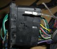
New Speaker Cables.111 viewsThis is the door connector, Main loom to Right, Door side to the left. to the top of the connectors you can see green and Green white wires which are the speaker ones. The door wiring is premium and has two pairs, the main loom was a 1 pair high line, so i am adding the pair you see (one already pinned up) to upgrade the loom to premium.
|
|
Halfords Booster Cables37 views
|
|
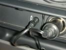
498 viewsRear iPod cabling solution. Notice the hole where the cables descend into the rear of the center console.
|
|

106 viewsPower cables passed through grommet
|
|
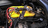
The auxiliary battery21 viewsThe auxiliary battery in the bay.
As the wiring diagram I made shows, there's a wire leading to the fuse box in the rear. (is going through the key-switch)
The second one is going to the fog lights. The smaller cables which should be connected to the head-lights, are connected to the battery.
The third one is going to the compressor (via a switch) (sits before the key-switch)
A fourth one is going to the CB and battery check display (sits before the key-switch)
|
|

12V to dual USB11 viewsAs the USB cables were running to the booth, I added a 12V to dual USB charger in the booth and connected the USB cables.
|
|

2037 viewsEverything pulled to bit\'s in order to get cables in for PC Screen etc.
Note the panel with USB and LAN connectors on, this replaces the LR panel with the ash tray in.
|
|
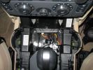
Here\'s a view of the Drive+Play "brain" which I mounted in the empty space in front of the gear selector.650 viewsI ran the power and audio cables to the rear of the center console in order to tap into the 12 volt power and "Aux" adapter. When you're sitting in the back seat, you don't see any cables whatsoever. My entire goal was to make it look as factory original as possible.
|
|
Thread upload28 viewsImage uploaded in thread 92518
|
|
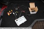
Everything thats included77 viewsCamera & GVIF and all cables after removal
|
|
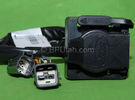
Harness section that runs behind the rear bumper.410 viewsThis is the harness section that clips up inside the rear bumper and includes the circular 7 pin, (6 flat +1 round), NAS socket, and also the 4 pin NAS flat connector.
The two small plug ends connect under the rear left tail light to the harness section that exits from the interior.
The Land Rover part number for the NAS trailer tow kit, (both cables), is YWJ500220.
|
|

Rosen A10 Land Rover Installation Manual841 viewsThis is a 11 page pdf which is the Land Rover version of the A10 installation manual for our 3. It consists of a hundred plus sketches showing how and where to connect various cables, conductors and plugs.
|
|

LTB00145 - Technical Bulletin - Remove & Install Parking Brake Cables90 views
|
|
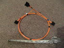
Fibre Optic MOST cable between components.561 viewsThis is a typical section of Plastic Optical Fiber (POF) optic cable with the orange coloured cladding covering the perimeter of the light transparent core. This is used as the MOST (Media Oriented Systems Transport) data transmission medium.
Note that each MOST 1355426 optical connector holds a pair of light conductor cables, one transmitting optical signal in, and the second, optical signal out. When connected to the other cables and devices, the cables form a continuous loop.
The light signal within the cable is red colour as one might expect. One break or disconnect anywhere along the loop shuts down signal transmission to all the connected components.
|
|
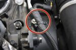
Tie-Wraps774 viewsWhen the EGR pipes are removed, you lose the brackets these cables are normally secured to because the brackets are part of the pipes. This is my solution to the problem - refit the bolts with an almost closed tie-wrap around them, then slip a new tie-wrap through the loop on that one and around the cable.
|
|

Thread upload19 viewsImage uploaded in thread 92518
|
|
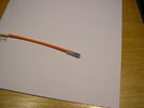
FL2 MOST cables72 views
|
|
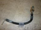
Negative Battery Cable209 viewsThis shows the corrosion from the negative terminal on the Negative to body ground. This is likely due to gas released through the negative post. It appears to be a common problem with the LR3. As a result of this corrosion left unchecked will damage the computer ecu and cables mounted near and below the battery.
|
|

d4 cables lose in boot40 views
|
|
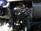
278 viewsA mess of cables. You can see the HD Radio antenna adapter coming out into the slot for the IHU. You can also see, if you look very closely, the original diversity antenna connector plugged into another adapter to go down to the HD radio unit.
|
|
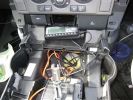
255 viewsThe console mostly re-assembled. You can see the dremel notch I made for the control cables, as well as the slack in the power and audio cables.
|
|
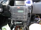
329 viewsInstallation slowly proceeding. You can see the controller cables inserted into the notch I made with a dremel.
|
|
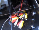
AV in and Output cables379 views
|
|
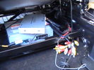
interface unit sat on dvd - cables pulled under seat frame410 views
|
|
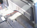
no need to remove this trim - cables easily go underneath them325 views
|
|
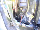
dead easy to get cables from boot to rear light cluster through existing grommets344 views
|
|

Where is the 12V Cable20 views
|
|
Thread upload4 viewsImage uploaded in thread 193079
|
|
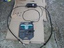
384 viewsOverview - box, two brake cables and release cable
|
|
1337 views
|
|
77 views
|
|

88 views
|
|
Thread upload15 viewsImage uploaded in new thread
|
|
Thread upload19 viewsImage uploaded in thread 108393
|
|
884 views
|
|
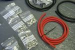
Take one box of cables and crimp fittings...103 views
|
|
|
|
|