| Search results - "cat" |
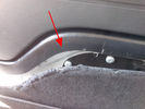
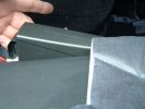
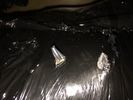
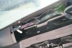
Rimozione pannello dalla sponda - Tailgate panel removing43 viewsPer togliere il pannello moquettato dalla sponda ho fatto leva con un cacciavite abbastanza grosso nel punto indicato, è stato veloce e non ho rovinato niente.
To remove the carpeted panel away from the tailgate I used a big enought screwdriver at the point indicated, it was fast and I have not ruined anything.
|
|
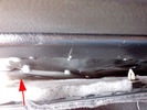
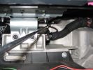
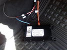
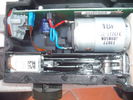
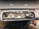
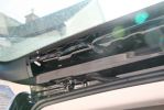
Riparazione attuatore sponda posteriore - Tailgate actuator repair37 viewsL'attuatore si trova dietro la pellicola nera incollata alla carrozzeria che va strappata.
The actuator is located behind the black film glued to the body must be torn.
|
|

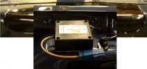
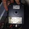
Chiave aperta11 viewsUna volta estratto il circuito stampato, facendo leva col cacciavite sulla parte rimasta attaccata ho prelevato la lama della chiave da inserire nel box nuovo.
Once you remove the printed circuit board, leveraging with the screwdriver on the part remained attached, I picked up the blade of the key to be inserted in the new box.
|
|
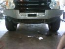
Fabrication Template Work258 views
|
|
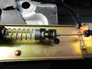
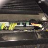
Cavo nel morsetto - Cable in clamp47 viewsHo inserito il terminale rotto nel morsetto: bisogna sforzarlo molto e ho praticato una cava attraverso il foro della vite con una punta in modo che il terminale non possa scivolare.
I entered the terminal broke into the clamp: you have to force it a lot, and I practiced a quarry through the screw hole with a bit so that the terminal can not slip.
|
|
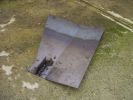
Steel compressor plate682 viewsIgnore my crappy welding attempts - I got a friend to finally weld the locator tab on the front!
|
|
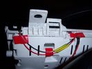
Insrument panel rear 31 viewsShowing wiring for heater and lights on indicator
|
|
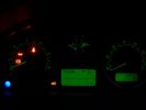
Insrument panel 33 viewsShowing heater and lights on indicator
|
|
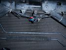
Chinese socket location13 views
|
|
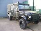
Catching Some Rays !20 views
|
|

Radio location537 viewsMy remote head UHF CB mounted on the front of the ashtray, ham HF/VHF/UHF remote head radio mounted on a block in the coin tray and my GPS on a turned wooden block in the cup holder. Both radios are under tha driver and passenger seat and the antenna for the GPS is suction mounted inside the windscreen.
|
|
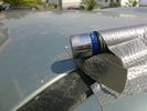
sophisticate ant-shake camera mounting3143 views
|
|
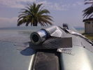
sophisticate ant-shake camera mounting2143 views
|
|
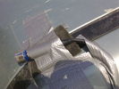
sophisticate ant-shake camera mounting1133 views
|
|
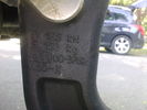
remouvable tow bar italian certification number122 views
|
|
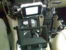
MONITOR STACCATO108 views
|
|

Chassis harness to main harness107 viewsDescription: Chassis harness to main harness
Location: Below LH rear wheelarch
Part No.: YPC909640 Colour: LIGHT GREY Cavities: 18WY
Harness: CHASSIS HARNESS
|
|

Thread upload5 viewsImage uploaded in new thread
|
|
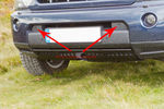
Front Camera Locations46 views
|
|
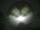
This is a normal H7 HID bulb installed in a BMW headlight to show glare above cut off line96 viewsThis is what the light pattern is that causes glare in most retofit applications including some projector lights. this is in fact a projector headlight on a BMW but the old projectors were only actually half projectors and half reflective bowls. the beam pattern should be clean cut like this ___/
|
|

1 General Information, Identification Codes and Jacking and Lifting24 viewsPart 1 of Discovery 3/4 Workshop Manual - General Information, Identification Codes and Jacking and Lifting
|
|
2 Nokia - Location of Nokia Module on trim71 views
|
|

2009 Ford ESP Extended Warranty Contract144 views
|
|

98 viewsCircuit breaker mounting location. Mounted with industrial velcro
|
|
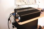
79 viewsCarPC closed and ready for mounting. Note the modification to the rear of the case to allow extra USB sockets attached to the motherboard pins.
|
|
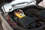
124 viewsOptima Yellow Top in battery box. This is the version with side terminals so there will be some modifications to be done to fit
|
|
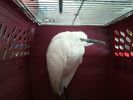
egret catch76 views
|
|

Opaque switch cover116 viewsKR switch on:off:on used for front and rear spots - but LEDs not visible with coloured switch cover!
(Located in sunroof switch position)
|
|

Terratrip 202 V4 possible discrete location134 viewsAttached to ashtray - allowing removal / unplugging when not in use by pulling out the ashtray.
Terratrip is an odometer for use in rallies / raids - very popular with the French when used in conjunction with a roadbook. A mechanical backup in case GPS signal is lost on modern odometers like the Globe 800 I propose to use.
We'll see if there are reflection issues from the screen.
|
|

Thread upload18 viewsImage uploaded in new thread
|
|

2017-07 JLRP00100 Service indicator message and oil dilution7 views
|
|

Brake shoe arm 17 viewsCable retaining spring location
|
|

Brake shoe arm20 viewsCable retaining spring location 2
|
|
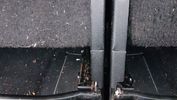
RAW jack1 viewsCasing just catches the inner legs of the seat backs.
|
|

Steering Column detailing Steering Angle Sensor1480 viewsItem 2 in the picture on page 1 of the 9 page pdf shows the location of the steering wheel sensor. Page 5 of the pdf has a paragraph describing the operation of the sensor. When the steering wheel does not point the same direction as the real wheels, then the computers can put the 3 into safe mode and down goes the suspension. See also the 17 page pdf on the Anti Lock and Traction Control pdf.
|
|

C0506R56 viewsDescription: ABS module
Location: Rear of engine compartment - driver side
|
|
TT Box Location144 viewsSmall TT box, easy to fit on spare battery compartment
|
|
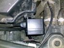
Possible Location for wireless remote box situated to the front of the airfilter housing108 views
|
|
Thread upload3 viewsImage uploaded in thread 198799
|
|

Air suspension Control Module98 viewsDescription: Air suspension Control Module
Location: RH 'A' post
Part No.: YPC500830 Colour: NATURAL Cavities: 20WY
Harness: CABIN HARNESS
|
|
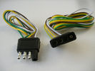
4 pin NAS flat connector from NAS small trailer377 viewsThe connector with the three exposed pins is the end that would commonly be located at the trailer hitch end, (front), of a small NAS lightweight trailer that has no electric brakes. This plug would connect into the flat 4 pin connector at the rear of the 3.
Note the order of the pin functions and wire colours: White is ground; the next pin is for tail/marker lights using the Brown wire; the Yellow conductor is for the left turn signal, and the far pin uses the Green conductor for the right turn signal.
There is no separate brake light conductor as NAS spec vehicles most often combine the brake and signal light functions to the same bulb filament rather separate filaments in different bulbs. The LR factory harness resolves that design difference.
Fortunately, the Land Rover NAS assembly pin order for the 4 pin flat plug maintains the above described conventions.
|
|

Air Distribution and Filtering Systems2045 viewsThis is 3 page pdf with coloured drawings of the air distribution ducting for the front air system.
Also included is a sketch of the pollen filter location within the front heater ducting. Note that two types of filters are available: a) the cheaper dust/pollen filter and b), the activated carbon filter that removes smells from the air. Installing the more expensive activated carbon filter means you never smell a cattle truck or chicken farm again. It really works.
|
|

Air Conditioner Specifications 4.4L V81539 viewsThis 2 page pdf is just the specifications for the AC system. The refrigerant type is R134A.
Note that when topping the system up, it can be a good idea to include some of that ultra violet light dye that will glow to show leaks and loose fitting.
|
|

Alternator and Regulator Wiring Diagrams, TDV6 and petrol V8 and V61973 viewsThis is a three page pdf that shows the alternator and regulator wiring for the petrol V6, petrol V8 and TDV6. The pdf can be either printed or by right clicking on the displayed pdf, rotated as required for viewing.
Of interest is that the regulator gets its instructions primarily from the Engine Control Module (ECM) and only secondarily from the vehicles electrical buss. The conductor from the battery thru the 5 amp fuse F20E is to provide initial power to excite the alternator at startup and then secondarily, to instruct it if the PWM signals were not available. Primary instructions to and from the ECM are thru the two other conductors via a digital like Pulse Width Modulated (PWM) signal.
If F20E, the 5 amp engine compartment fuse box fuse is blown, the red alternator light on the dash will be illuminated. This means that the alternator could be OK, but if the F20E fuse is blown, no electricity will be generated. Hence check the F20E fuse if you get a red ALT light or some indication of the alternator not working.
Regarding operation of the red ALT light on the dash, it is not the regulator within the alternator that tells the red light to illuminate, or not, but instead the ECM. This is the reason the red light does not function in the same manner as with older vehicles. With the 3, sometimes you have illumination and sometimes not depending upon what the ECM is thinking. What this means is that you can have an alternator that is failing but the red light does not illuminate as the ECM is compensating for reduced alternator output - maybe by draining the battery and or cutting back on vehicle electrical loads such as shutting off or cycling the radio amplifier or heated seats.
|
|

9 views
|
|

Fibre Optic MOST bus plus CAN, LIN, GVIF and SLIN buses1522 viewsThis 7 page pdf introduces the fibre optic MOST bus, (the orange coloured cables), the two high and medium speed CAN buses, the Gigabyte Video InterFace, Local IntercoNnect, and Security Local IntercoNnect buses.
|
|

GPS NAV system components and operation987 viewsThis 16 page pdf describes the operation of the GPS navigation system and provides pin outs and equipment layouts. The GPS antenna amp and location is also shown.
|
|

88 views
|
|
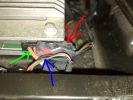
5 ICE Loom - Location of pre fitted Voice / Speed pulse connector67 views
|
|

Winery Located on the Biltmore Estate127 views
|
|

Sensor-Height-Rear-LH65 viewsDescription: Sensor-Height-Rear-LH
Location: Below LH rear wheelarch
Part No.: YPC909530 Colour: BLACK Cavities: 3WY
Harness: CHASSIS HARNESS
|
|

Connector: C210196 viewsDescription: Rear control valve
Location: Below LH rear wheel arch
Part No.: YPC800230
Colour: BLACK
Cavities: 6WY
|
|

37 views
|
|

Thread upload25 viewsImage uploaded in thread 135375
|
|

Thread upload30 viewsImage uploaded in thread 195682
|
|

Thread upload5 viewsImage uploaded in thread 175193
|
|

Optima Battery Specifications164 viewsOptima Battery Specifications
|
|
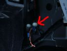
7 ICE Loom - Earth location B piller drivers side69 views
|
|

C2243R72 viewsDescription: Main harness to engine compartment harness Location: Behind passenger compartment fusebox
|
|
Thread upload3 viewsImage uploaded in thread 175209
|
|

Add A Circuit Littelfuse Data sheet2264 viewsThe switch connects to what Littelfuse brand calls an Add-A-Circuit model FMH200BP which is an adapter that plugs in place of a Mini fuse and then has space for two Mini fuses, (original and a second one). In this install, only the original 5 amp fuse was used - adapter was so as to route power from fuse box thru fuse, then rocker switch, and then back to fuse box.
Before you install the Add A Circuit for this application, take an ohm meter and trace out the circuit path of the four slots that fuses could insert into. The path is more complicated than one might first think. As such, the orientation of the fuse holder in the socket matters for this application - that is for a circuit diverter, rather than accessory adder.
|
|

Land Rover Aerial Fin images for both Glass and Metal Roof Disco3 / LR3850 viewsAs well as the two different fins, this pdf also shows the plastic blanking plate for glass roof vehicles where no fin is installed.
The glass roof fin is secured by two security screws from the top into a plastic frangible glue on gasket. The hope is that when struck, the fin will shear off and not crack the glass roof. Re the metal roof design, the fin is secured from underneath via two nuts.
The pdf also shows the various electrical bits related to the antennas. In the UK, the fin would house not only a cell phone antenna but the TV and satellite radio antenna electronics as well; in the States, the Sirius sat radio antenna and a G type cell phone antenna if the phone kit was installed would reside within the fin. The SAT NAV GPS antenna is located within the High Mount Brake Light plastic mounted to the upper rear hatch.
|
|
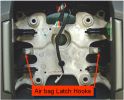
airbag latch hooks337 viewsAirbag retained to steering wheel by 2 latch springs located onto latch hooks of steering wheel
|
|
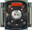
airbag latch springs321 viewsAirbag retained to steering wheel by 2 latch springs located onto latch hooks of steering wheel
|
|
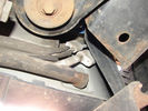
Air Conditioning Pipes (file 2)803 viewsShows location of front-to-rear air con pipes behind NS front wheel. You can just see the Vredestein tyre. The pipe connectors are tucked in behind the wheel arch inner cover. This has to be partially removed for access to bolts holding pipes together.
|
|
79 views
|
|

132 views
|
|

Alternator female plug looking down into top367 viewsThis shows the plug connected to the alternator wiring harness looking down into the top of the plug.
The cavity marked 1 is the AS or BATT SENSE and the wire colour most likely has Brown/Green on it.
The cavity marked 2 is the RC or ALT CON and the wire colour most likely has Red/White on it.
The cavity marked 3 is the L1 or ALT MON and the wire colour likely has Green/White on it.
I say "most likely" as the wire colours are not always the same on all vehicles.
Also the terminal 1 conductor destination is more likely C0570-175 rather than per the jpg.
The #3 pin is located closest to the big B+ terminal.
|
|

Thread upload11 viewsImage uploaded in thread 144407
|
|

Thread upload9 viewsImage uploaded in thread 144407
|
|

Setup Web application for Altox WBUS-458 viewshow to setup the Web application for Altox WBUS-4
|
|

Compressor type TSB106 viewsLand Rover TSB regarding Compressor type identification and fitment.
|
|

February in the sun!182 viewsNo D3 to drive but the weather and location was excellent!!
|
|

Thread upload4 viewsImage uploaded in new thread
|
|
Thread upload5 viewsImage uploaded in new thread
|
|

Thread upload14 viewsImage uploaded in thread 172891
|
|

Thread upload10 viewsImage uploaded in thread 174831
|
|

Thread upload5 viewsImage uploaded in new thread
|
|

Thread upload3 viewsImage uploaded in thread 190029
|
|
Thread upload13 viewsImage uploaded in thread 64916
|
|

Thread upload14 viewsImage uploaded in thread 64916
|
|
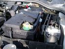
Aux Battery showing ground cable bolt "upside" down 1568 viewsIn order to obtain sufficient height clearance to get the plastic cover back on, I had to install the ground cable to the underside of the battery post connector.
Note the battery vent hose, (approx 5 ft required) is run down into where the windshield washer fluid container is located. There is not much electrical or metal in that area to be corroded by battery gas plus the open end of the vent hose tends to be protected from dirt and stays clean as well.
|
|
13 views
|
|

Frame Jacking Points showing where holes are located.1078 viewsThe four points marked with the arrows show where the holes in the underside of the frame are located such than one could insert a trolley jack pin type lifting adapter, (or as designed), the official LR scissors jack.
|
|
7 views
|
|

Caterpillar Battery Size cross reference chart and battery profiles including post layout749 viewsThis pdf has a dimension, (metric and inches), cross reference chart plus another sheet that provides BCI and DIN cross reference numbers and shows post locations plus bottom ridge tie down locations, (or the lack of).
This data was for me, hard to find, and helps one in selecting a suitable physical size of Aux battery for the space available.
|
|

265 views
|
|

34 views
|
|
Bluetooth modules location1332 views
|
|
Thread upload2 viewsImage uploaded in thread 200758
|
|

OLD VERSION - Bodsy's Brake Bible v 1.611087 viewsUSE Version 1.6a
Clarified EPB shoe instructions & corrected references to other sections. Added paypal donations information (requested by users of the guide.) Internationalised wheel location references by removing UK based reference to OS/NS, replaced with physical Front Left or Front Right descriptions.
|
|
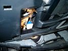
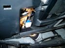
Brake Switch Visible thru Opening4933 viewsThe blue and white bit is the switch; the sort of gold appearing box,(it is really black), you will not see in your 3 as it is a Smooth Talker brand amplifier for my Blackberry phone antenna. This install is detailed in the SmoothTalker phone antenna section of my gallery.
One way to remove and install the switch is to lower the "horizontal" panel above the brake pedal as shown where the flashlight head is located. To actually remove the switch, you slide your hand thru the gap and rotate the switch clockwise 1/4 turn while watching thru the rectangular opening. Installation of the new switch is the reverse of above - 1/4 turn counterclockwise.
Before you remove the switch, note its orientation - horizontal with electrical wires to the left. That is the way it should look after replacement as well.
The second time I replaced the switch, I did it all thru the rectangular opening and did not remove the horizontal panel - that is experience helping out.
The knee kick you have to remove regardless. It is sort of hinged at the bottom so you just pull at the top and sort of rotate the knee panel and then pull upwards for two plastic "fingers" to clear the slots they reside in.
|
|
Smooth Talker Amplifier Box mounted below near steering column.179 viewsThe gold look box due to the lighting, (actually black), is the antenna amplifier located near the steering column. It can be put anyway but this seemed an OK location as I ran the antenna connector cable rearward from here to the back corner of the 3 and then up to the underside of the roof glass at the rear. The blue/white thing is the brake light switch that often must be replaced. See the Brake Light Switch file within this Gallery regarding the switch replacement.
|
|

77 views
|
|
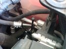
Vertical Breather Hose before cutting off OEM cap.1740 viewsThis shows the plastic vertical breather tubing and OEM cap prior to being cut off. The tubing is located on the driver side at the front near the radiator. One cuts about 3/4" to 1" off from the top. The TSB says 20mm.
I tried blowing thru the cut off piece and was not very successful. The cap seemed plugged. I am beginning to think that there was a very good reason for Land Rovers's Technical Service Bulletin, (TSB).
|
|
Thread upload1 viewsImage uploaded in thread 189350
|
|

Thread upload1 viewsImage uploaded in thread 189350
|
|

Fabrication Template Work217 views
|
|
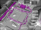
Camera Control Module D451 viewsHarness connection detail, camera module, located beneath L/H passenger side front seat UK D4 spec 2012.
|
|

Can Bus with splice locations1 views
|
|
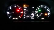
Car indicated temp30 views
|
|

11 views
|
|

82 viewsDescrizione struttura tenda (catalogo Conver mod. Orion4) da montare sul carrello per uso 4 persone
|
|

169 views
|
|

49 views
|
|

Thread upload21 viewsImage uploaded in thread 109817
|
|

7 views
|
|
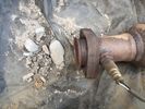
Thread upload15 viewsImage uploaded in thread 129774
|
|
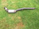
Thread upload3 viewsImage uploaded in new thread
|
|

Thread upload13 viewsImage uploaded in new thread
|
|

car audio technics leaflet but they quote £600 or something, not the price on here238 views
|
|

Thread upload28 viewsImage uploaded in thread 101191
|
|

Thread upload1 viewsImage uploaded in thread 195456
|
|

Thread upload11 viewsImage uploaded in thread 154409
|
|

105 views
|
|

Thread upload6 viewsImage uploaded in thread 151873
|
|

Thread upload1 viewsImage uploaded in thread 194599
|
|

81 viewsNear the petroglyphs the caterpillars were having quite a party.
|
|

144 views
|
|
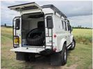
4 views
|
|
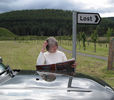
My lovely Cath, 'Lost' in deepest Aberdeenshire..72 views
|
|

Thread upload13 viewsImage uploaded in new thread
|
|

196 views
|
|

Thread upload2 viewsImage uploaded in thread 179950
|
|

Thread upload0 viewsImage uploaded in thread 197456
|
|

Thread upload2 viewsImage uploaded in thread 200758
|
|
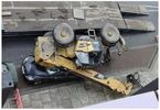
Thread upload2 viewsImage uploaded in thread 200758
|
|

Thread upload12 viewsImage uploaded in new thread
|
|

Thread upload8 viewsImage uploaded in new thread
|
|

Thread upload4 viewsImage uploaded in thread 180191
|
|

Thread upload3 viewsImage uploaded in thread 180191
|
|

Thread upload1 viewsImage uploaded in thread 180191
|
|

Thread upload1 viewsImage uploaded in thread 180191
|
|

Thread upload1 viewsImage uploaded in thread 180191
|
|

Thread upload6 viewsImage uploaded in new thread
|
|
night cat4 views
|
|
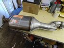
Thread upload1 viewsImage uploaded in thread 196887
|
|

Thread upload5 viewsImage uploaded in thread 180661
|
|

Thread upload3 viewsImage uploaded in thread 180661
|
|

Thread upload0 viewsImage uploaded in thread 200758
|
|

Thread upload12 viewsImage uploaded in thread 200758
|
|

Thread upload3 viewsImage uploaded in thread 179197
|
|

Thread upload1 viewsImage uploaded in thread 201035
|
|

68 views
|
|
Thread upload8 viewsImage uploaded in thread 165662
|
|

230 viewsCB location to right of stereo
|
|
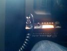
204 viewsCB location under steering wheel to left.
|
|
Thread upload3 viewsImage uploaded in thread 191052
|
|
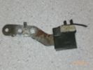
Condensatore (capacitor) 153 viewsZF catalog number 27.730 - LR number NNW502820
|
|
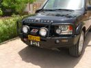
Front end326 viewsARB deluxe winch bar is very well made. Still allows Mantec sump guard to be used. Warn M8000 winch fitted - (wish I could\'ve found an M15000!) and IPF 900XS Extreme Series mounted with light stays to grille. Fog lights work fine with the replacement bumper, and indicators in bumpoer are effective too.
|
|
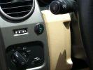
Long Ranger auxilairy fuel tank pump switch and tank gauge307 viewsFitted to the right of the air vent thumbwheel, the neat combination switch and gauge take sup no room at all. Switch locks on or off, but no pump running warning lamp! Contents of the tank are indicated by 5 LEDS, 4 green and 1 red for full, 3/4, 1/2, 1/4 and empty. Pump transfer rate of just 2 litres p/min is disappointing. I transfer on the move when main tank is at 1/4.
|
|
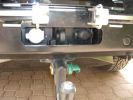
LR towing electrics pack 12N/12S312 viewsThe LR trailer electrics fitted before the Kaymar bumper and spare wheel carriers required no modifications are perfectly accessible. Good strong recovery point between the sockets too. The swing awau wheel carrier securing latches can be seen quite clearly here. Long Ranger tank (painted black) nestles where orignal spare was fitted.
|
|
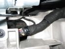
Follow pointer for location240 views
|
|
Follow the pointer for location238 views
|
|

Thread upload29 viewsImage uploaded in thread 190184
|
|

2006 Ducati 749r - first time touching down, 3rd day track riding, didn't know enough to be scared156 views
|
|

COMM FAILURE in the Faultmate FCR77 viewsThis is ONLY shown if either you have a communication error or in most cases you dont have fitted on your car the module you are trying to communicate with.
|
|

317 views
|
|

Thread upload0 viewsImage uploaded in thread 198377
|
|

118 views
|
|
On Board compressoe location52 views
|
|
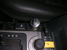
Controller 1145 viewsLocation of HK controller on top of EPB cover.
|
|

Cooling system hoses - 4.4L petrol V81098 viewsThese are the cooling system hoses on the 4.4L petrol V8. The little odd shaped bleeder hose, (LR006158), shown in the top right hand corner can give problems. There is a plastic tee with a threaded air bleeder outlet located in the middle of the hose. The plastic tee can or will fail due to I guess heat distress.
A BIC pen can serve as a field fix, however for your parts kit, a nominal 3/8" ID hose size brass hose barb inline connector plus a couple of hose clamps is suggested. Better yet is a threaded hose barb brass coupling or a tee and bleeder valve to allow bleeding of the line. Land Rover now makes the plastic bleeder valve that breaks available as a separate part, # LR027661, where 0 is a zero. As such, one can now purchase that part only for addition to your field fix parts kit.
|
|
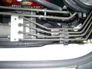
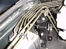
CounterAct Power supply mounted under brake lines.191 viewsThis top view shows where I located the power supply. It is attached with 3M sticky to the black plastic surface that is located under the brake lines.
When the system is operating properly, the red LED pulses about twice per second.
Some users claim they can hear a very slight hum or whine coming from the unit. My unit seems silent.
|
|

Countersunk Bolt Specification76 views
|
|

Portrait Of Crumble, her youngest horse, by Cath. See highlandpetportraits.co.uk for more68 views
|
|
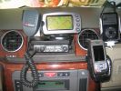
Information and Comms167 viewsUHF, Streetpilot, Mobile and iPod
|
|

U013223 viewsLost Communication With Ride Level Control Module
|
|

U013225 viewsLost Communication With Ride Level Control Module
|
|

U015535 viewsLost Communication With Instrument Panel Cluster (IPC) Control Module
|
|

U015537 viewsLost Communication With Instrument Panel Cluster (IPC) Control Module
|
|

D3-4 cambio ZF 6HP26-28_Catalog.pdf76 viewsD3-4 cambio ZF 6HP26-28_Catalog.pdf
|
|
143 views
|
|

Thread upload1 viewsImage uploaded in new thread
|
|
Thread upload12 viewsImage uploaded in thread 184914
|
|
Thread upload2 viewsImage uploaded in thread 198491
|
|

Part 1 of the LF Inset in Grill Installation221 viewsDetailes of the Grill preparation as well as the modifications needed to the front end.
|
|
D4 Bluetooth AH42 10F845 AA module connected to 12VDC and MOST1190 viewsThis jpg shows the MOST bus connected to the AH42 10F845 AA module used in the D4 as well as +12VDC power from F58P connected. The power is split with a Y harness as the IHU (radio) for some reason required +12VDC power to the C2115-10 "mute" pin to keep the radio/CD audio from muting all the time.
With power on the pin, the radio audio does mute as it should when the cell phone rings and the hands free connects. The brown conductor feeds to C2115-10 and the blue to the module.
The module tucks up and hides behind the grey plastic section covering the forward portion of the passenger side tranny hump for left hand drive vehicles; for RHD, it would be located on the left side.
The pairing code is 2121 with this setup and not 1234 or 0000.
|
|
D4 Fuel Temp Sensor Location 315 views
|
|

Thread upload0 viewsImage uploaded in thread 172895
|
|

Thread upload0 viewsImage uploaded in thread 172895
|
|
Thread upload0 viewsImage uploaded in thread 172895
|
|

Thread upload0 viewsImage uploaded in thread 172895
|
|
Thread upload0 viewsImage uploaded in thread 172895
|
|

Disco3 on the move in Dangalli Conservation Park - at speed (south of Yunta)177 viewsMusic heard in video is from the stero blasting away inside the Disco - and yes...that was a cattle grid being crossed at the start :-)
|
|
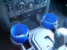
375 ml jam container369 viewsThese are the 375ml Danish Orchard brand jam containers. They fit fairly tightly into the original old style, (2005/6) Land Rover 3 factory cup holders. The extra height provided by the containers can be an advantage. I have a similar assortment of containers in some of the door panel located wine bottle holders to better hold containers of lesser valued products.
|
|

78 views
|
|

Thread upload21 viewsImage uploaded in thread 128544
|
|
Thread upload18 viewsImage uploaded in thread 128544
|
|
Thread upload17 viewsImage uploaded in thread 128544
|
|
Thread upload19 viewsImage uploaded in thread 128544
|
|

129 views
|
|

104 views
|
|

149 views
|
|
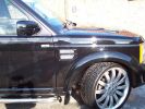
Bespoke Colour Coded side vent with Racing mesh93 views
|
|

Deka Battery Dimension Data613 viewsThe battery size that I installed for my auxiliary was a BCI 40R battery as it was for me the easiest to fit and was also a cranking battery. The case profile was such that no tie down fins were located on either bottom end, (sides yes), and length wise, it was only about 11" (290 mm) long. As such, I did not have to grind the nibs at the front bottom of the plastic surround.
I did however raise the bottom of the battery above the angled nibs as I set the battery on a 1" (25mm) high plastic spacer. The total height, (battery plus spacer), was about 8" (200mm) so the battery top still fit under the Land Rover factory cover.
For the Aux battery, when I replaced the 40R, I installed an Interstate BCI 47 which is similar in size to a DIN H5. I was therefore able to eliminate the vertical spacer as the Group 47/H5 is the same height as the DIN H7/H8 stock LR spec starting battery. As such, the standard battery tie down bolts can be used without modification. The Group 47 battery is 9 11/16" long x 6 7/8" wide x 7 1/2" (190mm) high.
|
|

Hardware location of wiring audio information and entertainment system2210 viewsHardware location of wiring audio information and entertainment system2
|
|

Antenna locations449 views
|
|
![Filename=dewalt-dcs380l2-cordless-18v-reciprocating-saw-c-w-2x-3_0ah-li-ion-batts-[3]-18045-p.jpg
Filesize=49KB
Dimensions=500x500
Date added=22.Aug 2013 dewalt-dcs380l2-cordless-18v-reciprocating-saw-c-w-2x-3_0ah-li-ion-batts-[3]-18045-p.jpg](albums/userpics/18918/thumb_dewalt-dcs380l2-cordless-18v-reciprocating-saw-c-w-2x-3_0ah-li-ion-batts-%5B3%5D-18045-p.jpg)
59 views
|
|
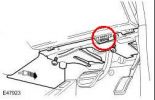
Diagnostic socket location105 views
|
|
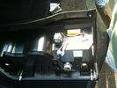
196 viewslocating of resistor to rear of D4 led lights and scotch blocks but theres loads of room so the choice is yours
|
|

Headlight mod and D4 grill mod62 viewsFirst tackle of mods to my D3, First attempt was the D4 grill, then the de-orange of the headlands, Also installed LED sidelights and indicators
|
|

D3 Torque specs56 viewsTorque specification for D3
|
|

specification sdv6 tdv642 viewscontains gear ratios and outputs
|
|

MY12 Discovery 4 Product Brief165 viewsDetails of changes, upgrades etc for MY12
|
|

Thread upload1 viewsImage uploaded in thread 201586
|
|

Thread upload1 viewsImage uploaded in thread 201586
|
|

Fast & Furious 618 viewsOn Location ...!
|
|
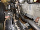
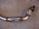
162 viewsDe-cat pipe
|
|
Thread upload11 viewsImage uploaded in thread 138866
|
|
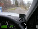
Display 1113 viewsLocation of D+P screen. Sticky pad used to attach to dashboard
|
|

Thread upload0 viewsImage uploaded in thread 198490
|
|

27 views
|
|

Location of the unit491 views
|
|
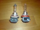
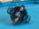
The H9 bulb have 2 locating lugs.260 views
|
|
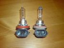
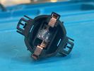
H9 on the left after modification266 views
|
|
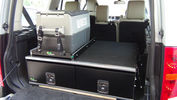
Ironman Drawers and Fridge Slide111 viewsI hate kitsets, over 100 bolts to assemble this unit and lost gallons of sweat, must have read the instructions a hundred times or more but final product does not look so bad. A few bolts hanging out the sides of both slide and drawers that may catch things so time will tell if I made the correct purchase.
Maybe one day I will make some side wings to cover the sides properly.
|
|

ding location131 views
|
|

The Shangri La Hotel, Muscat83 views
|
|
3rd Row Catch4 views
|
|
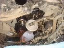
catching coolant - well nearly!67 views
|
|
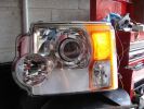
Indicator lamp with low wattage filament illuminated320 views
|
|
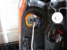
indicator lampholder, white wire connected to unused filament325 views
|
|
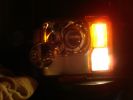
Indicator low power lamp & standard sidelamp illuminated289 views
|
|
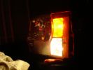
Indicator low power lamp & standard sidelamp illuminated, side view314 views
|
|
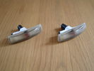
Smoked Side Indicators26 views
|
|
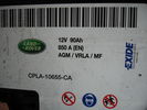
D4 Battery Specifications30 views
|
|
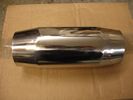
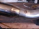
8 viewsWelded into a "replica race cat"
|
|
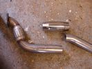
9 viewsPipe cut at location of cat on original pipe
|
|
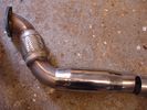
Adding a "Cat" to the decat pipe12 viewsReplica cat slipped over
|
|
15 viewsPipe spot welded together and "Cat" slipped over to the joint
|
|
15 viewsPipe welded together encompassing the "Cat"
|
|

Camera location in the middle top of the rear window395 views
|
|
Grommet on bulkhead easily located...77 views
|
|
Alarm fitted in suggested location for the circuit breaker - will either velcro-fasten to the alarm or find alternative location83 views
|
|
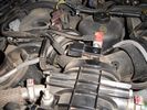
MAP location79 views
|
|
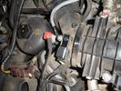
MAP location71 views
|
|
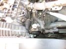
Water Temp sensor location929 views
|
|
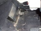
Internal water tank right side view160 viewsShows right front side of tank, with RH seat lifted. Note seat bolt is used to also hold the tank secure. This is a 5-seat D3, which has a cover over what is normally the 3rd row footrest. This is where the water tank is located.
|
|
catalonia july 1312 views
|
|
Scatola Freno di Stazionamento76 views
|
|
310 viewsLeft hand side impact absorber almost touching cooling system on NA spec truck. Absorber required modification.
|
|
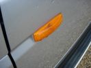
Discovery 3 side indicators199 views
|
|
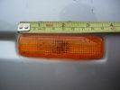
Discovery 3 side indicators213 views
|
|
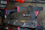
182 viewsAnother shot of the right slider. The center support channel has drainage channels welded in that match the locations of the drain holes on the sill frame.
|
|
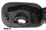
Foto 2115 viewsPer rimuovere in blocco il portello bisogna inserire un tondino del diametro di 2mm. circa nei fori indicati per abbassare le mollette che tengono la struttura alla carrozzeria Vedi foto 3.
Ogni lavoro � fatto a rischio e pericolo di chi lo fa, non mi assumo alcuna responsabilit� per eventuali danni causati a persone o cose.
|
|
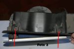
Foto 3 - Rimozione portello143 viewsInserire un tondino metallico di 2mm di diametro per abbassare le mollette che bloccano la struttura del portello.
Bisogna anche rimuovere il dispositivo della chiusura centralizzata indicata dalla freccia grigia della foto 4 premendo le 4 linguette con due pinze.
Ogni lavoro � fatto a rischio e pericolo di chi lo fa, non mi assumo alcuna responsabilit� per eventuali danni causati a persone o cose.
|
|
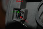
Foto 4 - Rimozione particolare rotto156 viewsUn'alternativa per rimuovere il pezzo rotto (indicato dalla freccia rossa), anzich� smontare tutto il portello si pu� intervenire inserendo un cacciavite piatto come indicato dalla freccia verde, al fine di sollevare la linguetta indicata dalla freccia verde della foto 5. Questa linguetta sblocca il perno del particolare rotto indicato dalla freccia verde della foto 1.
Ogni lavoro � fatto a rischio e pericolo di chi lo fa, non mi assumo alcuna responsabilit� per eventuali danni causati a persone o cose
|
|
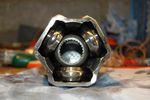
Bearings correctly located108 views
|
|

Thread upload0 viewsImage uploaded in thread 178790
|
|
33 views
|
|
29 views
|
|

27 views
|
|

Thread upload2 viewsImage uploaded in thread 187407
|
|
Location of oil filter on 2006 TDV6350 viewsLocation of oil filter on 2006 TDV6
|
|
Thread upload10 viewsImage uploaded in thread 199883
|
|

Thread upload0 viewsImage uploaded in thread 183644
|
|

Fuel Purge Valve and other hoses.838 viewsThis 6 page pdf shows the Fuel Purge Valve and associated hoses and describes how it is supposed to work. There are lots of good drawings of the fuel system. It is more complicated than one might think.
|
|
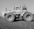
My favourite 4wd , spent thousands of hours farming with this. Sold it in immaculate condition.128 viewsVery well engineered Tractor. 16 Fwd grs,4 speed P/Shift weighed 1800 lb alone (if I remember correctly), 4 equall sized clutch packs, alternates 2 lay shafts with clutch packs, dry sump. no master clutch or TQ/C,Cat 3306DTA. 1 of 12 in Australia.
|
|

53 viewsfbh fuse location in engine bay fuse box
|
|

After130 viewsIt's lights indicator now !
|
|

Before128 viewsMY05 Instrument cluster + Software upgrade
FBH indicator instead of lights indicator !
|
|

61 views
|
|
Thread upload8 viewsImage uploaded in new thread
|
|
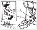
Water Filter Location261 viewsThe water filter (if youy have one) might be fitted adjacent to the water pump connection
|
|

Thread upload0 viewsImage uploaded in thread 198799
|
|
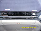
FM/AM/TCM Location53 viewsThis is the location and connections for the FM/AM and TCM
|
|

Hi Line antenna locations28 views
|
|

Ford News Cover Story May 2006216 viewsFord News is a monthly publication (aka propaganda!) magazine, given to all Ford workers. This months issue has a lead article about the TDV8. Thought it might be of interest.
|
|

Exploded Parts view calling up 6R60/80 and 6HP26/28 variations3094 viewsThis single page jpg exploded parts view indicates some commonality between the Ford and ZF versions of the early and later six speed units. Technically this sheet is for the RWD units as there are variations between plain RWD units, 4WD, and AWD. The transmission in the LR3 is called by ZF to be a 6HP26X and by LR in some publications, the 6HP26
|
|

Calendar 2010291 viewsLand Rover Discovery 3 in Southern Namibia. A private road constructed by my employer to service cellular base stations. The location is Frederickshoop in the South of the country. 500m drops made this terrifying.
|
|
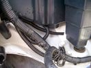
Front Coupler pad to right front under air filter housing 155 viewsThe brighter white "square" behind the black air cleaner drain is the Coupler Pad location I chose for the right front corner. The 1/4", (5mm), black wiring loom carries a single blue colour conductor between the power supply and pad.
A second coupler pad, (white conductor), is located near the left rear tail light. The mounting location is accessible from the rear compartment access "door" where the trailer hitch wiring attaches to the factory loom.
|
|

LED Mirror Covers64 viewsLED Indicators & Welcome Lights in the Mirrors
|
|

70 views
|
|

66 views
|
|

front camera location11 views
|
|

Cat sells dog on ebay148 views
|
|

Thread upload16 viewsImage uploaded in thread 109662
|
|

FUSE SPECIFICATION CHART66 views
|
|
24 views
|
|
Glovebox 1141 viewsLocated D&P box on underside of glovebox, same as LR iPod/MP3 box
|
|
Stragglers Catching Up102 views
|
|
GPS antenna & location111 views
|
|
Thread upload8 viewsImage uploaded in thread 179812
|
|

Oil specifications for land Rover models193 views
|
|

Drive & Play148 viewsFitted the screen using a piece of laminate flooring fibreboard underlay & cutting up a 3.99 leatherette cushion, looks like it was fitted from new
|
|

Rear heater line relocation190 views
|
|

Thread upload1 viewsImage uploaded in thread 157814
|
|

Thread upload1 viewsImage uploaded in thread 157814
|
|
Thread upload2 viewsImage uploaded in thread 148106
|
|
Thread upload2 viewsImage uploaded in thread 148106
|
|
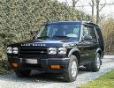
Heavy Duty Disco92 viewsMy first Disco after some modifications...with Photoshop at least.
|
|

Thread upload190 viewsImage uploaded in thread 162283
|
|

IGN Live Location27 views
|
|

President Johnson II in its current position16 viewsThis CB was installed some years ago and still is at the same location.
However, I'm planning to move it to the head unit area.
As such, I'm looking around to replace my low end head unit with a single DIN radio and the CB on top of it.
|
|

Led location - red led on left A pillar 25 views
|
|

secret shrine21 viewslocated in a secret place tgis old shrine is all that remains of an old buddist temple
|
|

preserved species26 viewscat anyone!!
|
|
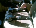
639 viewsCup holder panel showing the 8 locating lugs and clips
|
|

Puzzle - how do I get to that cat on the other side?47 views
|
|

9 views
|
|
Harness location15 viewsArea of harness that chafes against battery terminal
|
|

CV boot puncture 83 viewsThis is how the cat was returned from the garage
|
|
Jodrill bank145 viewsPhoto taken whilst delivering telecommunications equipment
|
|
Cat alitic converter !11 views
|
|

EAS Aftermarket Modification.18 viewshttp://www.mudtech4x4.com
|
|

Before Modification203 views
|
|
Cat alitic converter10 views
|
|
Evohome application6 views
|
|

Headlight mod266 viewsHeadlight mod to my07 land rover discovery 3
|
|

LP scoped 218 viewsBy connecting a Low Amps probe to the fuel pump's voltage supply wire, you can view the pump's current waveform on a digital storage oscilloscope (DSO). The scope pattern will reveal internal wear in the brushes and commutator that may not show up in a traditional pressure or volume test.
Observing the waveform will show if the pump's amp draw is normal for the application or is high or low, and if the pump is operating at normal speed or is running slow. Problems such as a bad spot on a commutator or a short or open in the armature also will be obvious in the waveform.
A "good" electric fuel pump waveform will generally seesaw back and forth with relative consistency and minimal variation between the highs and lows. A "bad" waveform will show large or irregular drops in the pattern, with large differences between the highs and lows.
|
|
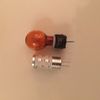
D4 indicator bulbs led 36 views
|
|
cablaggi sotto sedile67 viewsoggetto nn meglio identificato
|
|
cablaggi sotto sedile96 viewsaltro oggetto non meglio identificato presente sotto entrambi i sedili
|
|
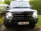
NEW LED SIDE LIGHTS AND INDICATORS (headlight MOD complete baby)88 views
|
|
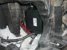
1630 viewspicture showing the location of the "Lodar" radio winch remote control box.
|
|
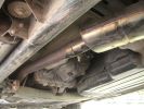
Stainles joins after the cat's626 views
|
|
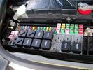
Picture of the engine compartment fuse panel5752 viewsEngine compartment fuse panel located near the battery. This is where F3E, (5 amp), F26E, (20 amp), Fuseable link 10E, (60 amp) and Relay 7E, the now upgraded 70 amp air compressor motor relay, part number YWB500220, (E is for Engine compartment fuse box), are all located. Fuse F35P, (5 amp), is inside the Passenger compartment behind the lower glove box door.
To keep the suspension from going down to the stops when driving, (or parked), it appears that it is only really necessary to remove F26E to depower the exhaust valve and generally keep all the valve block solenoid valves in a closed position trapping whatever air is within the air springs. F3E gets its power thru F26E, so when F26E is removed, the F3E circuit is automatically de-powered. F35P is more interesting in that battery power goes thru the ignition switch and F35P and then into the air suspension control unit. Apparently however, if F26E is removed, removing the F35P is not needed even when the engine is running.
With all fuses still in, if you have a problem, in practice, ideally, the compressor still works and will raise the 3 to an appropriate height. If so, one can then shut the engine off and allow the computers to go to sleep and then you remove the fuse(s). In actual practice, it seems that one need only pull the F26E fuse and can do so with the engine running. All the same, one might consider that the 3 is first a mobile computer, and secondly a 4x4. Computers prefer to go to sleep before the plug is pulled on them, however given that F26E circuit is always alive, then the computer never sleeps. With the fuse(s) pulled, and if you are still up, you can now be a 4x4 instead of a low rider. The whole purpose of the fuse pulling exercise is to depower the one and only system exhaust valve that is physically located within the compressor unit, (to keep it from opening), and secondarily to keep closed the four air spring solenoids within the block valves. This also shuts the air compressor down and stops the air compressor from making air even if the compressor is still good. That is why you initially need the fuse(s) in to allow the compressor to make air if it can.
|
|

98 viewsPlug removed from left hand side of dash to locate wires from clove box
|
|
My dedicated road wheels!59 views
|
|
Bottom of airbox, showing one-way valve and locating lug176 views
|
|
GVIF Button Location45 views
|
|
D4 Lowest Grade Radio - Screen Closeup70 viewsThe monochrome screen with colour-lit icons on the left to indicate source, and bluetooth icon on the right to indicate connectivity. There are also two hardware buttons for hour/minute clock setting.
|
|
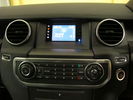
D4 Lowest Grade Radio - Wide Angle75 viewsThe CD player is at the bottom of the picture, the control buttons in the middle, and at the top is the screen with colour-lit icons on the left to indicate source, and bluetooth icon on the right to indicate connectivity. There are also two hardware buttons for hour/minute clock setting.
|
|

D4 height controller switch location36 views
|
|

D4 height controller switch location 252 views
|
|

Cat front end loader144 views100 Ton low bed pulled by a Volvo FM 16 610 hp TT.
|
|

Cat front end loader147 viewsWorking weight of 103 tons, mass as loaded on trailer +/- 90 ton.
|
|
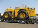
Cat front end loader142 views
|
|
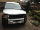
Modification work, nice birdy13 views
|
|
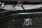
This is the cable in relation to the catch77 views
|
|
3104 viewsindicators & wheel centres upgraded
|
|

LED indicator 92 Ultrabright LED71 views
|
|
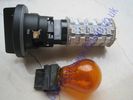
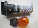
LED indicator vs standard capless 315659 views
|
|
led 3156 indicator bulb61 views
|
|
What film location?133 views
|
|
Arch 17 viewsDamage to locating pins
|
|

Bastogne Cathedral32 views
|
|
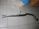
decat pipe46 views
|
|

Few More Mods...5 viewsGloss black mirrors, Black Discovery Bonnet lettering, clear indicator repeaters, gloss black air vent grille.
|
|
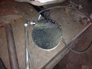
CAT13 viewsOpened CAT, First section.
|
|
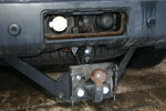
Modified Thule 9705 plate42 viewsShows the adapter plate after modification to improve departure angle
|
|
TMC amp location showing antenna button68 views
|
|
TMC amp location49 views
|
|

LRO18556 Clock spring and indicator/wiper stalk29 views
|
|
Harmon Kardon Audio Amplifier10 viewsLocated underneath right hand front seat. Connected to MOST system
|
|
Nokia Bluetooth Module12 viewsLocated behind side panel of right hand luggage area. Connected to MOST system
|
|
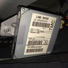
TMC Module11 viewsLocated behind side panel of right hand luggage area
|
|

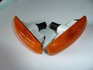
Clear door indicator lenses6 views
|
|
Thread upload5 viewsImage uploaded in new thread
|
|

Thread upload0 viewsImage uploaded in thread 202239
|
|

Thread upload6 viewsImage uploaded in new thread
|
|
Thread upload0 viewsImage uploaded in new thread
|
|

160 views
|
|

Interstate Battery Dimension sheet640 viewsThis sheet is hard to find - the sheet is not on the Interstate corporate web site but some dealer web sites display it. The pdf shows most of their available batteries including the H7 and H8 sizes that are the LR North America replacement batteries for the main starting battery. These batteries are of the Land Rover desired "shallow" cycle high discharge current Maintenance Free, (Ca Ca), internal construction, (not AGM, but instead, Wet Flooded Lead Acid with battery "caps" and Ca grid separators).
For the AUX battery , the H6, (BCI Group 48), is probably similar in dimensions to the Varta E12V75N that is popular in Australia. For that battery to fit in the second battery compartment, you must grind out the angled nibs on the inside front bottom of the LR black plastic surround, something I did wish to do and hence installed a Group 40R on a spacer. Alternately, one can choose an Interstate BCI Group 47 which is similar to a DIN H5 for the AUX location. I did this when I had to replace my 40R. No vertical spacer is required and the stock battery tie down bolts and clamp work well.
|
|

JAE connectors for the upper hatch switch and FAKRA connectors for the Sat NAV.537 viewsThis jpg shows some catalog pages listing the MX19 connectors used on the upper hatch switch.
Also shown are the FAKRA connectors that are used on the rear of the Sat NAV.
|
|

Thread upload5 viewsImage uploaded in thread 152911
|
|

Thread upload5 viewsImage uploaded in thread 152911
|
|
Thread upload19 viewsImage uploaded in thread 151252
|
|
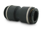
John Guest DOT all plastic fitting714 viewsThis is a picture of the John Guest DOT all plastic union. If you look closely, you can see the DOT imprinted in raised letters on the end of the fitting. This is of a 1/4" connector rather than the 6mm that the 3 requires.
The picture is similar to the air suspension pneumatic fitting union that Land Rover sells as replacement part # STC8580. This is for 6mm OD tubing size. The STC8580 comes with what are called "Collets" at each end that cover up the press to release feature underneath. See the John Guest web site www.johnguest.com under the Pneumatics section and also in Downloads for their catalog for install and remove instructions.
The actual "air brake spec" fitting that Land Rover provides has an interior 4mm OD ferrule that slips inside the 4mm ID of the nominal 6mm tubing. I have not yet been able to obtain the John Guest part number for the LR fitting, only the LR part number. This part number was generated for the RR Classic air systems.
|
|

John Guest (LR part # STC8580) push in straight 6mm tubing to tubing connector727 viewsThis picture is similar to the air suspension pneumatic fitting union that Land Rover sells as replacement part # STC8580. This is a 6mm OD tubing size push in to install straight tubing to tubing fitting. The STC8580 comes with what are called "Collets" at each end that cover up the press to release feature underneath. See the John Guest web site www.johnguest.com under the Pneumatics section and also in Downloads for their catalog for install and remove instructions.
The actual fitting that Land Rover provides has an interior 4mm OD ferrule that slips inside the 4mm ID of the nominal 6mm tubing. Hence the fitting depicted and part number are not actually correct. I have not yet been able to obtain the John Guest part number for the LR fitting.
The fittings that show in this doc are what I call food service fittings rather than transportation or Air Brake fittings. The part LR sells, (STC8580), is the Air Brake type for transportation.
|
|

Key in Ignition Electrical Wiring Diagram1043 viewsThis shows the key in ignition wiring, (LGW, 1.5D), running from the key lock cylinder to the Central Junction Box, (CJB), thru 5 amp fuse F40P, located in the fuse box behind the lower glove box door.
You can remove the 5 amp fuse and the good news is that the ignition chime will not sound any longer; the bad news is that a bunch of other circuits that rely on knowing if the key is in or out no longer work.
Also note the Transponder Coil D219 reference.
|
|

Auto dimming mirror connector22 views
|
|

Modification so that the headrest is adjustable833 views
|
|

Modification so that the headrest is adjustable1015 views
|
|

Modification so that the headrest is adjustable818 views
|
|

Modification so that the headrest is adjustable1082 viewsmax. height
|
|

Modification so that the headrest is adjustable781 views
|
|

LA100-002 - Technical_Bulletin - Lubricant and Fluid Specifications277 views
|
|

LA303-001 - Technical Bulletin - Cylinder Head Built to Supercharged Specification66 views
|
|
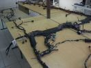
Wiring Laid out shown from other side121 viewsDamaged Disco 3 loom on bottom and new Sport one on top. This angle is as if you were looking at the drivers seat from the front (RHD). You can see the amp wiring centre shot and the rear door wiring to the left all duplicated.
|
|

Thread upload4 viewsImage uploaded in new thread
|
|

Piped out after a two and a half year rebuild! A 90 V8.73 views
|
|

10 views
|
|

LED trailer lights adapter for LR3831 viewsThis doc includes a partial list of materials and the instructions/links required to construct an adapter to prevent LED trailer lights from pulsing due to the 3's diagnostic circuits interrogating the signal light circuit.
Using the adapter also facilitates the green flashing of the dash located trailer indicator when the signal lights operate plus inhibits operation of various systems such as the backup sensors, etc.
|
|

Thread upload16 viewsImage uploaded in thread 108943
|
|
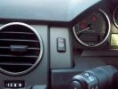
Lights On Indicator218 views
|
|

Thread upload5 viewsImage uploaded in thread 159579
|
|
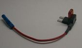
Littelfuse Mini Add-A-Circuit FMH200BP and OFH0200ZP1610 viewsFound this jpg somewhere on the forum - others are using them as it is a good way to tap the fuse box to add a fused circuit, or in this case, to modify a circuit to add a switch such that the fused circuit is switched. In my SmoothTalker gallery, there is a PDF from Littelfuse specifically related to this Add-A-Circuit device.
Before you install the Add A Circuit for any application, take an ohm meter and trace out the circuit path of the two pair of slots that fuses could insert into. The path is more complicated than one might first think. As such, the orientation of the fuse holder in the socket may matter depending upon the application. If the application is a circuit diverter, (as the F35 mode is), as opposed to a mere accessory adder, orientation matters.
|
|
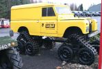
Forestry LR Caterpiller 123 views
|
|

File - Load Retention System - VUB503130.pdf245 viewsPDF extracted from Premier Automotive Group (T/AS Land Rover Australia) publication number L3879.
|
|

Thread upload16 viewsImage uploaded in thread 52130
|
|

Thread upload5 viewsImage uploaded in thread 184969
|
|

LR Electric Trailer Brake C2590 Female Connector598 viewsThis female connector, C2590, located up above and near the brake pedal is for the Trailer Electric Brake Controller hookup.
The Black wire in the bottom right is pin #3, the ground. The Blue wire to the left is pin #6, the Trailer Brake Controller output going to the rear trailer socket.
The White #4 wire is the 30 amp fusible link, (Link 6E in the engine compartment junction box), for the Brake Controller 12VDC power feed from the battery. Note that this would make a pretty good power source for CB radios and the like if no electric trailer brakes were required.
Pin #5 is a Green wire from the stop lamp switch, (the control input for the Brake Controller).
This plug is standard on all NAS (LR3) vehicles, but unlikely to be found on the D3 spec units.
|
|
Thread upload1 viewsImage uploaded in thread 156108
|
|
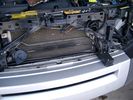
19mm wiring loom in trough behind bumper and in front of rad790 viewsThe 19mm wiring loom is large enough that a maximum of six 6mm air lines can be fished thru as required. The loom runs from the FASKIT panel located in the engine compartment behind the left front headlight, down and across in front of the rad and then down to the front axle valve block located behind and below the right fog light.
|
|

LR3 Air Conditioner Drain Tubes behind centre console2091 viewsThis shows the two air conditioner drain tubes located left and right under the radio stack.
The tube on the left side, (steering wheel side, LHD), disattached itself and the carpet on the floor under the gas pedal etc became soaked. I think rain water from outside that comes in the outside cowl vents also exits via the tubes as I first noticed the carpet was wet after parking outside during a big rain storm.
It was relatively easy to slide up and reattach the rubber hose that runs from the rectangular shaped plastic discharge hole(s) of the heater "pan" down along the transmission hump area and thru the floor pan. There is a hose on each side of the transmission hump, but only one hose had let go on my 3. The rubber hoses just slide over the rectangular plastic openings of the two heater housing drain outlets.
To get at each drain hose, remove the vertical sort of triangle carpeted piece below each side of the radio stack. The triangles of carpet will just pull away as each is held on with those metal U clips Land Rover so likes. Dislodge each triangle at least sufficiently to get ones hand in to slide the rubber hose back on.
You will rarely see AC water on the ground as the front drains pour onto a metal underside protection skid plate and the rear drain onto the top of the left rear muffler.
|
|
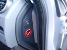
Air Suspension ECU Fuse 35P cut off switch.3802 viewsThis shows the SPST rocker switch mounted in the blank plate installed in lieu of a manual passenger side air bag shut down switch - now automatic via passenger seat pressure switch. Fuse 35P (5 amps) is located in the interior fuse box behind the lower glove box and protects the ignition power supply to the Air Suspension ECU. When the SPST switch is moved to the OFF position, the RAISE /LOWER switch on the centre console is not powered, and hence does not function. As such, some signals from the wheel height sensors and CPU are ignored. By itself however, removing F35P will probably not stop the 3 from self dropping, particularly after the engine is turned off.
Fuse F3E, (5 amps), located in the engine bay fuse box by the starting battery protects the circuit that provides feedback to the Air System ECU indicating that the Compressor Relay has successfully operated and that the Air Compressor is or should be operational, can also be removed, (but is probably not totally necessary), as it gets its power thru F26E. Hence Fuse F26E, (20 amp), also located in the engine compartment fuse box is the fuse that must be removed. This fuse protects the circuit that provides full time battery power to the Air System ECU. When in place, current thru the fuse powers the periodic re-levelling action, (usually lowering a bit with that brief air release noise), that often occurs when the vehicle is parked and the engine is off.
Removing F26E fuse will stop the auto levelling action and also inhibit any other down to the stops signals, (engine running or not). When F26E is removed, no power can flow thru to F3E, hence removing F3E is more for insurance than an absolute requirement. The same with F35P, removing F26E removes primary full time power from the Air Suspension ECU, and hence removing the F35P fuse should not really be required either as long as F26E has been removed.
|
|

Battery Maintainer pigtail sticking out of Grill723 viewsThis is all you see when everything is put back together - just the pigtail and Weather Pack blanking plug. Most often, I have it all tucked back behind the grill.
In winter, there may be a second cord hanging out as well - the 120 VAC power cord for the engine block heater, a tea kettle like element inserted in the engine block. NAS petrol V8's do not have the Fuel Burning Heater, (FBH), installed, but instead in cold area markets have the block heater element assembly available as a dealer installed option. There is an argument to say that the heating element is factory installed in all cold climate V8 gasoline engines, however the appropriate power cord is not. If true, this means that all one needs to purchase is the area specific power cord and plugging in / attachment to the engine block located block heater.
As such, you will often see a conventional 120VAC three prong power plug hanging loose out of the grill of most vehicles here in the wintertime. In summer, most drivers tuck the plug back behind the grill as it is no beauty mark.
|
|
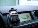
BlackBerry Tour 9630 mounted on air vent264 viewsThe antenna amplifier is mounted lower near the steering column. The amplifier box is painted black but looks sort of gold coloured due to the lighting in the other jpg showing the amp located under/near the steering column.
|
|
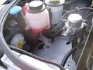
Empty space in NAS LR3 for location of FASKIT panel595 viewsThe empty space is available as the North America Spec gasoline engine LR3's do not have the Fuel Burning Heater installed. The air lines from the four air springs and the air tank will appear to rise up from under the headlight assembly. The lines to the front block valve assembly located behind the front right fog light will sort of run within the bumper across the front of the radiator down into behind the righthand fog light. The rear lines somewhat follow the path of the existing air feed line from the front valve assembly to compressor. Rather than be located between the left front fender liner and left metal wing however, the four lines will feed thru the empty wing space inside and above the wheel well arch and exit down by the left front mud flap. From there, the lines run along the left frame member above the air tank and then parallel the frame over top the compressor to the top of the rear left air spring where the rear air block valve assembly is located.
|
|
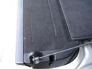
Flexible wire rope fishing leader 0.032" diameter exiting carpet 1931 viewsThis is all you see of the completed mod.
The short little angled "line" about an inch long that looks like a piece of debris and is located a few inches "above" the support cable is actually the wire rope release cable exiting from under the carpeted lift gate cover.
I drilled a very small hole in the carpet and pushed the 0.032" diameter release wire thru and then slipped the loose end under the black plastic.
To release with the lift gate etc closed, from the inside, just pull the loose end free from under the black plastic and gently pull wire about 5mm, (1/4"), and the upper door catch should release. You will have to manually push the upper door out wards to actually effect opening, but you will already be inside the rear cargo area so that part is easy to do.
The assumption is that the lower door latch still works electrically and hence, the lower lift gate half will open as normal by pressing the usual button on the top left of the lower door half.
|
|

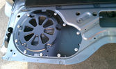
Carpet Panel Removed showing Bass Speaker and Dust Shield 1722 viewsSomething is wrong with the orientation, however this shows what you see when the carpet is removed.
The dust shield, (under which the actuator is located), in the picture is as yet uncut. The white bit is the underside of the plastic lower lift gate carpeted cover panel.
The round thing is the woofer speaker for the Harmon Kardon radio. When the radio is working, one can see the speaker moving, but not much bass sound actually seems to emanate from the speaker.
|
|
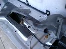
Dust seal rolled back showing electrical conductors 1647 viewsNote power conductors just under the dust seal which makes cutting the seal more interesting.
Also shown are the two 8mm nuts located in slots. One must loosen each nut to effect removal of the actuator. This will then reveal two T15 Torx screws that one must completely un-thread to remove the top gold plate from the actuator assembly.
|
|

NAS 7 Pin Round Socket + 4 Pin Flat Socket oriented as installed.742 viewsThis is the layout you see when you look into the NAS Land Rover sockets as installed at the rear of the LR3/4. The flat 4 pin socket is located under the round socket.
Wiring order is relative to the slot on the round socket, and hence the same as the other jpg where the slot is shown at the top.
The CJB monitors the front and rear turn signal lamps and can detect if more than four lamps are fitted, (the side turn signal lamps are not monitored). This is another reason for using genuine LR bulbs as off shore bulbs can have varied and out of spec resistance values.
When a trailer is detected, the trailer warning indicator in the instrument cluster is supposed to flash green in synchronization with the turn signal indicators.
If one or more of the turn signal lamps on the vehicle or the trailer are defective, the trailer warning indicator will cease to flash any longer. This is to alert the driver to probably bulb failure.
If the trailer has LED lamps installed, and no LED adapter circuitry is used, most likely the trailer will not be sensed and systems such as the backup sensors will not be disabled.
|
|

Wheel cut thru definitions and specs894 viewsNote the location of REAR SPACING and also OFFSET; probably two of the most important dimensions and not always understood as related to wheel size and relationship to the brake components.
For the 3, Rear Spacing is approximately 6.5 inches or 165 mm for a nominal 8" rim. Offset is 53P or 53mm Positive, which means the distance from the machined hub flat mounting surface to the rim's true centreline is 53 mm in the outboard direction. (The rim illustrated has a negative offset.)
As Positive offset increases, this means the wheel wraps around the disc brake mechanism more deeply, and hence the more the wheel would cover the brake parts. This is why most 18" wheels will not fit with the larger Brembo "supercharged engine" brake calipers.
Pitch circle diameter is 120mm; Pattern is 5 lug, and the tyre load rating is 112 with a recommended tyre speed rating of H or higher along with the XL load rating. For the 3, the stock tyre diameter is about 30 inches. The 255/60/18 or 255/55/19 OEM tyre outside diameter is 30.04 inches; Wheel lug torque is from 130 to 150 Nm or 96 to 110 lbf-ft and the lug nut hex socket size is 22mm.
Max Load High Speed Driving Tyre pressures are Front, 33 psig, (230 Kpa) and Rear, 42 psig, (290 Kpa).
The OEM rims are rated at 940 kgs, the highest that LR makes, hence while rims from other Land Rover products may physically fit, the odds are they are under rated in a weight sense.
|
|

Underhood Fuse and Relay Box drawing 3041 viewsShows the various fuse and relay locations. Fuse 3E, (5 amp), and Fuse 26E, (20 amp), as well as upgraded 70 amp Relay 7, part number YWB500220, locations are displayed. Relay 7 sends battery power to the compressor from the 60 amp fusible link called up as 10E. Fuse 26E is what provides full time always on battery power to the air suspension ECU and hence powers the auto level wakeup when the vehicle is shut down and say parked for the night. Removing F26E is the primary method to disable the air suspension system; Removing F35P is more if you want to experiment with it from inside.
I found it useful when I had a suspension problem, (actually a wheel alignment problem picked up by the steering wheel angle sensor), that only showed itself on the highway but allowed for no trouble light driving in the city. This was because in the city, the steering wheel was always in motion and rarely was the vehicle driven in a near straight line for very much distance.
|
|
19 mm wire, (tubing), loom rising from below at left headlight653 viewsFrom the FASKIT panel, five air lines fit in the 3/4" (19mm) wiring loom and feed to the front air valve block located behind and under the right front fog light.
|
|
Wiring (tubing) loom at left headlight showing FASKIT panel 582 viewsThis shows the wiring (tubing) loom and FASKIT panel mounted to left wing. The loom moves a a couple of inches (50mm) towards the bottle once the headlight is put back in as there is not enough free space for the loom as located. The FASKIT panel is just visible at the top left corner of the picture.
|
|
Wiring, (tubing), loom exiting temporarily from the front right fog light.566 viewsThe front axle air valve block is located just behind and below the fog light. Access to the valve block is by removing the right front fender liner, (or the bumper). The FASKIT lines are attached to the left and right front air spring lines at this location; also compressor air is taken from this location as well. Cutting the lines at as few different locations makes it easier to find leaks at a later date. As above, five 6mm air lines run from the FASKIT panel to the front axle air valve assembly and run within the loom. Two pair of the lines are for control of the air springs, and the fifth line taps the air supply at the valve block assembly off the compressor. This will be the air source line rather than tapping in directly to the high pressure air tank.
|
|
| 546 files on 2 page(s) |
 |
1 |  |
|