| Search results - "circuit" |

Tagliare per eliminare parte del coperchio - Cut to remove part of the cover14 viewsE' meglio prima levare il circuito stampato e poi la lama della chiave, per evitare di danneggiarlo. Tagliare sopra il tasto superiore per rimuovere solo la parte con i tasti.
Is better to remove the printed board first then the key, to prevent damage. Cut over the top button to remove only the part with the buttons.
|
|

Estrarre il circuito stampato con la batteria - Exctact the printed board with the battery18 viewsRimossa la parte superiore del contenitore, estrarre il circuito stampato sollevandolo leggermente dalla parte della batteria.
Removed the top of the box, pull out the printed circuit board slightly lifting from the battery side.
|
|

Chiave aperta12 viewsUna volta estratto il circuito stampato, facendo leva col cacciavite sulla parte rimasta attaccata ho prelevato la lama della chiave da inserire nel box nuovo.
Once you remove the printed circuit board, leveraging with the screwdriver on the part remained attached, I picked up the blade of the key to be inserted in the new box.
|
|
Circuit diags front page94 views
|
|

100 viewsCircuit breaker mounting location. Mounted with industrial velcro
|
|
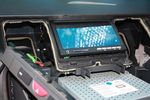
109 viewsTest fitting the screen. The bottom edge of the rear cover of the screen has been already dremeled off in this pic, notable as the circuit board can be seen.
|
|
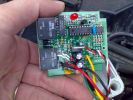
Front of Superwinch Remote Circuit94 views
|
|
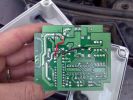
Rear of Superwinch Remote Circuit Board85 views
|
|
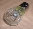
Land Rover Stop Tail Light dual filament bulb nominal 12 volt 21 / 5 watt filaments1428 viewsThis is the Land Rover part number 264590 dual filament bulb, (P21/5), that inserts into the upper two tail lamp receptacles. In the upper one, both filaments function, in the lower one, only the 5 watt tail light filament functions.
I regard it as not a good practice to routinely switch bulbs when the tail light filament, (5 watt), burns out on the lower bulb. The broken filament can jiggle over onto the brake light filament, (21 watt), and short the circuit to ground or something else not predicable.
There are also arguments to say that quality control is better on the Land Rover marketed bulbs than say far east sourced bulbs. Filament construction, and hence resistance can vary and mislead the current sensing circuits monitoring the signal light systems. Also when the bulbs are properly installed, all filaments should be standing vertically and not at any slope.
These are the sort of obscure circumstances that can lead to false trouble messages on the display, dropping to the stops, and subsequent concerns - all over a tail/signal light bulb.
For example, the filament life of both the tail light and the brake light filaments in the P21/5 bulb is significantly less than the USA common 1157 dual filament bulb, (1000/250 vs 5000/1200 hours); brightness in the P21/5 is a bit more, (3cp/35cp vs 3cp/32cp where cp is candle power), but current consumption is oddly less, (0.44a/1.86a vs 0.59a/2.10a where a is amps). It is the quest for efficiency vs maintenance trade off.
|
|

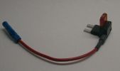
Add A Circuit Littelfuse Data sheet2279 viewsThe switch connects to what Littelfuse brand calls an Add-A-Circuit model FMH200BP which is an adapter that plugs in place of a Mini fuse and then has space for two Mini fuses, (original and a second one). In this install, only the original 5 amp fuse was used - adapter was so as to route power from fuse box thru fuse, then rocker switch, and then back to fuse box.
Before you install the Add A Circuit for this application, take an ohm meter and trace out the circuit path of the four slots that fuses could insert into. The path is more complicated than one might first think. As such, the orientation of the fuse holder in the socket matters for this application - that is for a circuit diverter, rather than accessory adder.
|
|
368 views
|
|
Thread upload1 viewsImage uploaded in thread 746
|
|
Thread upload1 viewsImage uploaded in thread 190256
|
|

Thread upload3 viewsImage uploaded in thread 196159
|
|

Brake Light Switch, Find, Remove, and Install Instructions 7854 viewsThis is a two page doc outlining where to find the brake light switch, how to remove it, and then install the new one.
Note, do not move the brake pedal when removing or installing the switch. Let the brake pedal hang where it wants to. The switch design is actually cunning, and as such is supposed to make the removal and install fool proof. Hence if you think too much about it, you can wreck the new switch.
If you want to inspect the interior of the switch, wait until you have removed the old switch. You can then just unsnap the blue from the white to get it apart. Inside, the switch is quite simple, (no circuit boards), but it will probably show black dust from failing contacts.
I think the reason the switch fails is that the Normally Open, (NO), contacts of the brake light contacts were made too light to carry the current load for make and break of the tail light filaments. I also think the black dust created then fouls the Normally Closed, (NC), second set of contacts for the ABS circuit. As such, the Normally Closed contacts become intermittent in operation and display as a fluctuating open and closed circuit condition to the ABS system when the ABS should be seeing a steady closed circuit. Hopefully the replacement switch contacts are more robust and may be as I recently replaced my switch again just as a matter of maintenance. While in a redesign, ideally the NC contacts should be sealed or at least separated from the NO contacts, when I inspected the removed switch, this time there was no black dust present.
Probably the removed switch will have a Land Rover oval logo moulded into it, the new one, FOMOCO.
|
|

Central Door Locking Operation Description1458 viewsThis 17 page pdf explains how the door locks are supposed to operate. Note that on page 9/17, the explanation of the operation of the hood ajar switch is wrong. It operates similar to the door and tailgate ajar switches; that is when a "door" is closed, the switch is closed to maintain a ground back to the CJB. Opening the hood, door, or tailgate removes the ground breaking the circuit and hence allows for an alarm condition.
|
|
Rear end294 viewsLocally made wheel covers. LH is zipped from bottom to top to fit over registration plate with zip fasteners top and bottom. Rear IPF Reversing /camp lights on rack linked to reverse light circuit.
|
|

circuit breaker110 views
|
|

placement of 1k resistor112 views
|
|

Thread upload3 viewsImage uploaded in thread 39609
|
|
Thread upload9 viewsImage uploaded in new thread
|
|

1 views
|
|
Thread upload4 viewsImage uploaded in thread 154757
|
|
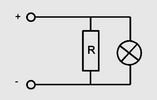
Circuito per collegamento frecce posteriori D4 su D366 viewsLa resistenza deve essere da 12 Ohm, 10 Watt minimo
|
|

183 views
|
|

Circuit of Ireland77 views
|
|
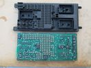
central junction box, without fuses.204 viewsthe print circuit board is easily dropped, after you pull out all the fuses.
|
|

181119 viewsif it had a P infront of the code it would be Four-wheel drive low ratio - short circuit to ground
|
|

B1C6258 viewsBATTERY SAVER OUTPUT CIRCUIT
|
|
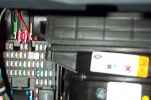
Tapa-circuit388 viewsTapa-circuit fitted to fuse box behind glove box. Red cable to top is the fused output cable leading to the PDA charger
|
|
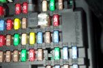
Tapa-Circuit Fuse Tap411 viewsTapa-circuit fuse tap fitted in existing fuseway provides extra fuseway which I have used to hard wire my Tomtom Sat Nav PDA. The fused output feeds into a female socket (Cigar lighter sized) into which the tomtom power adaptor is plugged. All hidden away behind the glove box.
|
|
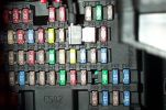
Tapa-circuit Fuse Tap435 viewsTapa-circuit fuse tap fitted in existing fuseway provides extra fuseway which I have used to hard wire my Tomtom Sat Nav PDA. The fused output feeds into a female socket (Cigar lighter sized) into which the tomtom power adaptor is plugged. All hidden away behind the glove box.
|
|
Hard wired tomtom498 viewsThe fused output from a tapa-circuit feeds into a female socket (Cigar lighter sized) into which the tomtom power adaptor is plugged. All hidden away behind the glove box.
|
|

Discovery 3 Exterior Light Wiring69 views
|
|
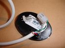
In readiness for soldering the remote wiring to the circuitboard61 views
|
|
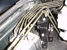
Alarm fitted in suggested location for the circuit breaker - will either velcro-fasten to the alarm or find alternative location88 views
|
|
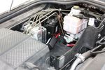
119 viewsCircuit breaker at other end of power cable
|
|

Thread upload37 viewsImage uploaded in new thread
|
|
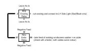
Retro fitted Headlamp Washer Relay Rewiring Circuit Diagram301 views
|
|
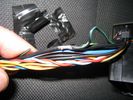
Earth or -Ve connection required under Driver Seat. Cut the green and black and splice into the blac.134 views
|
|
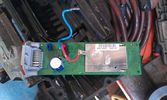
other side of epb circuit board93 viewsother side of epb electronics
|
|
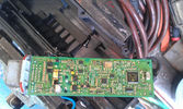
circuit board1 epb89 viewsThe circuit board inside your EPB
|
|

Topside of the circuit board145 viewsLooks better from the top :D
|
|

2015 SD card sat nav open circuit39 views
|
|
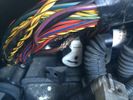
Harness chafing19 viewsWire insulation worn through with short to battery
|
|
B1591 324 viewsB1A56-11
Antenna - Circuit short to ground
Diversity antenna amplifier circuit short to ground
Refer to the electrical guides and check the diversity antenna amplifier circuit and the antenna for short circuit to ground
|
|
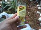
Add a circuit19 views
|
|
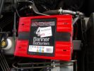
Aux Battery1054 viewsShows the aux 65Ah battery in place, top left of the picture is the 100amp circuit breaker feeding items sutch as , inverter, sub bass amplifiers, computer.
|
|
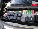
Picture of the engine compartment fuse panel5780 viewsEngine compartment fuse panel located near the battery. This is where F3E, (5 amp), F26E, (20 amp), Fuseable link 10E, (60 amp) and Relay 7E, the now upgraded 70 amp air compressor motor relay, part number YWB500220, (E is for Engine compartment fuse box), are all located. Fuse F35P, (5 amp), is inside the Passenger compartment behind the lower glove box door.
To keep the suspension from going down to the stops when driving, (or parked), it appears that it is only really necessary to remove F26E to depower the exhaust valve and generally keep all the valve block solenoid valves in a closed position trapping whatever air is within the air springs. F3E gets its power thru F26E, so when F26E is removed, the F3E circuit is automatically de-powered. F35P is more interesting in that battery power goes thru the ignition switch and F35P and then into the air suspension control unit. Apparently however, if F26E is removed, removing the F35P is not needed even when the engine is running.
With all fuses still in, if you have a problem, in practice, ideally, the compressor still works and will raise the 3 to an appropriate height. If so, one can then shut the engine off and allow the computers to go to sleep and then you remove the fuse(s). In actual practice, it seems that one need only pull the F26E fuse and can do so with the engine running. All the same, one might consider that the 3 is first a mobile computer, and secondly a 4x4. Computers prefer to go to sleep before the plug is pulled on them, however given that F26E circuit is always alive, then the computer never sleeps. With the fuse(s) pulled, and if you are still up, you can now be a 4x4 instead of a low rider. The whole purpose of the fuse pulling exercise is to depower the one and only system exhaust valve that is physically located within the compressor unit, (to keep it from opening), and secondarily to keep closed the four air spring solenoids within the block valves. This also shuts the air compressor down and stops the air compressor from making air even if the compressor is still good. That is why you initially need the fuse(s) in to allow the compressor to make air if it can.
|
|
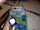
Move pin on circuit board28 views
|
|

Key in Ignition Electrical Wiring Diagram1052 viewsThis shows the key in ignition wiring, (LGW, 1.5D), running from the key lock cylinder to the Central Junction Box, (CJB), thru 5 amp fuse F40P, located in the fuse box behind the lower glove box door.
You can remove the 5 amp fuse and the good news is that the ignition chime will not sound any longer; the bad news is that a bunch of other circuits that rely on knowing if the key is in or out no longer work.
Also note the Transponder Coil D219 reference.
|
|
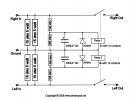
LED tamer circuit1007 viewsThis circuit is and will remain my property unauthorized commercial exploitation is forbidden.
|
|

Thread upload13 viewsschematic diagram of LED NAS light
|
|

LED trailer lights adapter for LR3844 viewsThis doc includes a partial list of materials and the instructions/links required to construct an adapter to prevent LED trailer lights from pulsing due to the 3's diagnostic circuits interrogating the signal light circuit.
Using the adapter also facilitates the green flashing of the dash located trailer indicator when the signal lights operate plus inhibits operation of various systems such as the backup sensors, etc.
|
|

Littelfuse Add-A-Circuit MINI and ATO style data sheet151 viewsPDF from Littelfuse showing both the MINI and ATO style of fuse holders. The 3 uses the MINI size of fuse. The MINI Add-A-Circuit can be inserted in place of one of the existing fuse panel MINI fuses. The removed fuse is then inserted into the lower slot of the Add-A-Circuit and a second fuse in the second slot to protect the device that you are adding. The Add-A-Circuit is designed for a max of 10 amps on the second load, and I guess maybe the original circuit as well.
|
|
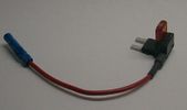
Littelfuse Mini Add-A-Circuit FMH200BP and OFH0200ZP1623 viewsFound this jpg somewhere on the forum - others are using them as it is a good way to tap the fuse box to add a fused circuit, or in this case, to modify a circuit to add a switch such that the fused circuit is switched. In my SmoothTalker gallery, there is a PDF from Littelfuse specifically related to this Add-A-Circuit device.
Before you install the Add A Circuit for any application, take an ohm meter and trace out the circuit path of the two pair of slots that fuses could insert into. The path is more complicated than one might first think. As such, the orientation of the fuse holder in the socket may matter depending upon the application. If the application is a circuit diverter, (as the F35 mode is), as opposed to a mere accessory adder, orientation matters.
|
|
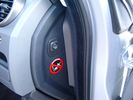
Air Suspension ECU Fuse 35P cut off switch.3821 viewsThis shows the SPST rocker switch mounted in the blank plate installed in lieu of a manual passenger side air bag shut down switch - now automatic via passenger seat pressure switch. Fuse 35P (5 amps) is located in the interior fuse box behind the lower glove box and protects the ignition power supply to the Air Suspension ECU. When the SPST switch is moved to the OFF position, the RAISE /LOWER switch on the centre console is not powered, and hence does not function. As such, some signals from the wheel height sensors and CPU are ignored. By itself however, removing F35P will probably not stop the 3 from self dropping, particularly after the engine is turned off.
Fuse F3E, (5 amps), located in the engine bay fuse box by the starting battery protects the circuit that provides feedback to the Air System ECU indicating that the Compressor Relay has successfully operated and that the Air Compressor is or should be operational, can also be removed, (but is probably not totally necessary), as it gets its power thru F26E. Hence Fuse F26E, (20 amp), also located in the engine compartment fuse box is the fuse that must be removed. This fuse protects the circuit that provides full time battery power to the Air System ECU. When in place, current thru the fuse powers the periodic re-levelling action, (usually lowering a bit with that brief air release noise), that often occurs when the vehicle is parked and the engine is off.
Removing F26E fuse will stop the auto levelling action and also inhibit any other down to the stops signals, (engine running or not). When F26E is removed, no power can flow thru to F3E, hence removing F3E is more for insurance than an absolute requirement. The same with F35P, removing F26E removes primary full time power from the Air Suspension ECU, and hence removing the F35P fuse should not really be required either as long as F26E has been removed.
|
|
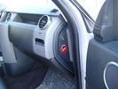
Air Suspension ECU Fuse 35P Shut Off Switch2636 viewsA more distant view of the shut off rocker switch in the ON position which is the normal position for when all is working as Land Rover intended.
Ideally, (but not totally necessary), the F35P circuit should be powered or de-energized after the various computers have gone to "sleep".
Similarly, removal of the F26E or F3E fuses is preferable after the computers have all gone to sleep but it appears that no real damage will be done if the fuses are removed while the system is energized. Pulling F26E is the main full time fuse that powers the air suspension computer. As such, once F26E is removed, pulling F3E is not really required.
Power for the compressor goes thru the 60 amp fusible link and relay, however control of the relay is via the air suspension computer so depowering the air suspension computer effectively depowers the air compressor and the internal exhaust valve relay/port.
|
|

NAS 7 Pin Round Socket + 4 Pin Flat Socket oriented as installed.752 viewsThis is the layout you see when you look into the NAS Land Rover sockets as installed at the rear of the LR3/4. The flat 4 pin socket is located under the round socket.
Wiring order is relative to the slot on the round socket, and hence the same as the other jpg where the slot is shown at the top.
The CJB monitors the front and rear turn signal lamps and can detect if more than four lamps are fitted, (the side turn signal lamps are not monitored). This is another reason for using genuine LR bulbs as off shore bulbs can have varied and out of spec resistance values.
When a trailer is detected, the trailer warning indicator in the instrument cluster is supposed to flash green in synchronization with the turn signal indicators.
If one or more of the turn signal lamps on the vehicle or the trailer are defective, the trailer warning indicator will cease to flash any longer. This is to alert the driver to probably bulb failure.
If the trailer has LED lamps installed, and no LED adapter circuitry is used, most likely the trailer will not be sensed and systems such as the backup sensors will not be disabled.
|
|
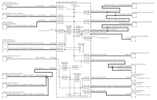
Power Window Circuit centered on Central Junction Box (behind glove box fuse panel)736 viewsRelay 143, the power window relay, and most other relays and FET's as well are built into the back of the passenger side behind the lower glove box fuse panel.
As such, the relays etc are not removable, jump-able, or serviceable.
|
|
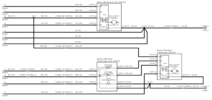
Power Window Circuit Sheet 2 Central Junction Box to Passenger Front Switch365 views
|
|

Power Window Circuit Sheet 3 Central Junction Box to Rear Switches393 views
|
|
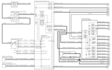
Power Window Circuit Sheet 1 from Battery to Central Junction Box (fuse box behind glove box)353 views
|
|

LR3 Electrochromatic Interior Rear View Mirror wiring diagram.854 viewsIt seems that there are two fuses, F69P and F5P that provide power for the interior rear view mirror. Ten amp F5P is a feed off the reverse gear relay and inhibits auto dimming when reverse is selected. Five amp F69P provides power to the auto dimming circuits and the garage door opener function if optioned.
The pdf can be downloaded and printed out. For on screen viewing, right click on the pdf and select the Rotate Clockwise button.
|
|

LR3 Denso Alternator YLE500390 pulley view819 viewsNote the DENSO sticker on the side. Denso calls their nominal 150 amp 12 Volt alternator an SC2 design. SC means Segment Conductor which apparently increase the winding density of the stator coil, hence yielding a physically smaller lighter alternator for a given output. I presume the 2 means the second try at getting it right. A Denso part number is 4280003690 for the alternator, (there are others, as below).
Rotation is clockwise and the 54mm diameter pulley has 6 grooves (PV6x54). Count the pulley grooves on both the one you remove and your new one - some replacement alternators seem to ship with 5 or 7 grooves so you might be swapping pulleys.
A previous LR part number was YLE500190 for the older variation of the newer YLE500390 unit.
An additional part number for a factory rebuilt is Nippon Denso 210-0569 for the petrol V8 alternator. Other Nippon Denso numbers include 104210-3690 and 104210-3691. The Lester number is 11206 which relates to another Denso number of 290-5287. WAI uses 11206N.
From 2006 to 2009, the internal regulator is a Transpo IN6349 and of the B circuit type if it can be said that applies to PWM, (Pulse Width Modulated), regulators.
The "regulator" inside the alternator is therefore really not a regulator in the old sense of the term but instead an instruction receiver from the ECM that translates Pulse Width Modulated (PWM) signals into a form that the alternator understands – digital like signals from the Engine Control Module(ECM) into analogue like signals that the windings understand.
|
|

LR3 Brake Wear Sensor Wiring1517 viewsThis 1 page wiring diagram pdf shows that both the front and rear brake pad wear sensors are part of a closed series circuit to ground.
In operation, when all is good, the series circuit is grounded and the amber brake wear warning indicator on the instrument panel is not illuminated.
When the pads on one wheel, either the left front, or right rear, become too worn, the respective sensor is "cut" which results in an open circuit condition. This causes the dash brake wear indicator to illuminate.
The circuit is like the old style Christmas light strings where one burned out bulb caused the whole string to go out.
A quick field fix to get the dash light to extinguish in lieu of replacing the sensor and pads etc is to disconnect the brake pad wear sensor and short across the two open conductors of the vehicle side connector plug. This of course means you now have a normal vehicle, one of the thousands that do not feature brake pad wear information systems.
|
|

Power Door Lock Wiring694 viewsAbove is a 5 page, (pages 222 to 226), pdf wiring diagram for the power door locks for the LR3.
You can download and print as required. For on screen reading, use the right click rotate feature.
Additional pdf's regarding Locks can be found within the Gallery under the Power Windows and Door Lock Circuits heading.
|
|

Horn Wiring Circuit LR3578 viewsThe is the wiring diagram for the dual horn circuit.
The Horn Relay, (R133), is not a big black thing hidden somewhere but instead what is called a FET, (and it is hidden)!
This is a Field Effect Transistor that is built into the circuit board that is mounted to the back of the fuse box that is located behind the lower glove box door on the passenger side of the 3. The related 15 amp fuse, 12P, is mounted in this fuse box and is often called F12P, where F is for fuse, and P is for Passenger compartment.
This is to help differentiate from another fuse and relay box, (the usual kind), that is located beside the starting battery in the Engine compartment. FxxE is often used in the naming of those fuses.
|
|

Stop Light Lamp Circuit pdf2492 viewsThis pdf shows the brake light circuit for the NAS LR3.
Note that power for the brake light bulbs can come either thru the brake light switch power feed /contacts plus also from the Hill Decent Control, (HDC), system relay located within the Central Junction Box, (CJB) - yes two separate sources of power for the brake light bulbs. This would tend to explain how a brake light circuit concern shows up as a hill decent fault message; also why lesser vehicles without hill decent braking mechanisms, (HDC), never display this sort problem when a brake light bulb or switch acts up. You never have a problem related to a system that does not exist.
Additional evidence of the relationship of the HDC and the tail light circuit is demonstrated by when the HDC actually acts to slow the 3 down, the brake lights automatically illuminate even if the slowing action was merely retarding the engine speed or shifting to a lower gear, (in other words, no foot on the brake pedal).
There is also a tie in to the Cruise Control and hence a failing brake light switch can affect cruise operation or just create false Cruise Control messages. To further complicate the issue, while there are no messages generated, operation of the radiator electro viscous fan can also be negatively affected by the fouled set of secondary contacts within the brake light switch. This is all because the NC contacts within the brake switch send misleading messages to the ECU.
While the ground wire design is similar to other vehicles, note the grounds for the brake light filament and the reverse light filament are common on each side. That means that if one has a non functioning brake light on one side, the reverse light may not also work or that some problem with the reverse lights could back feed into the brake lights. This situation while unusual, can result when grounds are corroded probably due to swimming in rivers and creeks or just routine driving in a marine environment.
|
|

LTB00180 - Technical Bulletin - Supplemental Restraint System Power Circuit Discharge59 views
|
|
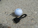
MOST fiber optic loop tool469 viewsThe looping tool in the jpg uses the Land Rover type plastic fiber optic cable with both ends feeding back into a female fiber optic connector that mates with the male fiber optic connectors on the Land Rover system.
The purpose of the loop is to allow one to disconnect MOST connected items such the BlueTooth module or the HK amplifier but allow the MOST system to still transmit signal from the head unit as the circuit would remain closed and hence complete. Of course with the Bluetooth module disconnected, there would be no Bluetooth available, however the radio and NAV would still function.
The looping tool allows one to troubleshoot the system by removing one component at at time from the MOST loop. In other words, what might appear to be a radio problem could be a Bluetooth problem - that sort of thing.
|
|

Thread upload1 viewsImage uploaded in new thread
|
|
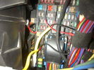
Fuse Panel showing F35P Add A Circuit installed1242 viewsFive amp fuse F35P is located towards the top left in this jpg. The other three Add A Circuit devices are for other items - powering my cell phone base etc.
Note the orientation of the Add A Circuit as this matters. Also one can just see a red tab sticking out from behind the device. The red is the conductor crimp end of a narrow 2.8mm male spade type connector that inserts into one of the "fuse" slots.
|
|

279 viewsSilverstone Circuit.
The first proper trip off-road. Raised £1400 for the Air Ambulance Charity doing ride-arounds for people at the Silverstone Classic. Hasten to add it wasn't just me!
|
|

Power Window Wiring Diagrams417 viewsThis pdf shows the power window wiring diagrams which are also shown as jpgs 1,2 and 3 below.
|
|
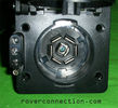
NAS 7 pin + NAS 4 pin Flat Trailer Socket309 viewsThis is the vehicle end of the NAS trailer harness that is located behind the removable plate centered within the rear bumper by the towing loop. Re the four pin flat connector, from the bottom, the exposed bare lower pin is the ground, usually the White wire on a NAS trailer. The next pin up is normally a Brown wire on a trailer and is for the Tail Lights. The third pin, normally a Yellow wire, is the left signal light; the top pin, normally a Green coloured wire, is the right signal light.
Re the round connector, from the notch in the plastic surround, clockwise, the first blade is ignition controlled +12VDC battery power, (only alive when engine running), and on the Land Rover factory harness is an Orange wire; on a NAS trailer, usually Red but perhaps a Black wire.
Next blade clockwise at 3:00 o'clock above, is the Right Turn signal light, a Green wire on the LR harness, and also on a NAS trailer.
At 5:00 o'clock, the next blade is for the Electric Brakes and is Blue on both the LR harness and on a NAS trailer.
The Ground wire is next, White on both the LR harness and on a trailer.
At 9:00 o'clock above, is the Left Turn signal, Yellow on both the LR harness and on a trailer.
The last blade to the left of the line up notch is the Tail Light circuit. On the LR harness, the wire colour is Brown with two White stripes and on a NAS trailer, Brown.
The centre pin is for the Reverse Back Up lights and is Black on the LR harness and often Purple on NAS trailer wiring but can be Black also.
Note that when the socket assembly is installed on the 3, the notch in the plastic surround is on the left - that is rotated 90 degrees anticlockwise to the picture above. In other words, When installed on the 3, the 4 pin flat connector lays horizontal and is located below the round socket.
|
|
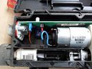
The lid is off!428 viewsShows motor, circuit board and left cable inner end
|
|
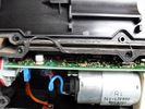
Circuit board and motor368 views
|
|

399 views
|
|

Tekonsha Ford Brake Controller Adapter part number 3035-P275 viewsThis is the adapter cable between the Brake Controller and the existing C2590 female plug located near the brake pedal on NAS spec LR3's. The flat 4 pin plug of the adapter cable connects to the Controller; the rectangular 6 hole male plug to C2590.
There are only four conductors in the adapter cable, but one will see five pins within the Land Rover C2590 plug. The #2 pin is not required for the NAS setup. #2 pin is the circuit between the head lamp switch and vehicle side running lamps required in the civilized world.
The single pin at the bottom in the picture is #3 and on the Land Rover, a Black wire tied to ground. The other pin at the bottom and across to the left is #6, and Blue on the Land Rover. This is the Brake Controller output to the trailer socket at the rear.
#4 is the pin at the top left, and is a White coloured wire from the battery. Pin #5 is from the stop light switch, and is Green on the Land Rover.
Note that the adapter cable colours do not necessarily follow all the above referenced Land Rover colours.
|
|

354 views
|
|
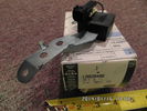
Radio Noise Filter Transmission Electronic Control Unit915 viewsThe jpg shows part number LR020488, a noise suppression capacitor located underneath on a bracket on the right side of the transmission forward of the selector shaft lever. The suppressor is connected to the transmission wiring harness and prevents solenoid operating noise affecting the audio system.
Failure of the capacitor is most often discovered as a result of either black smoke from below and or the blowing of 10 amp fuse F30E located in the engine compartment fuse box. This fuse protects the power circuit to the Transmission Engine Control Unit. When the fuse blows, the engine will still run however you have no gears, hence movement of the 3 is inhibited.
Anything over eight years in service is considered good capacitor life. If the capacitor does fail and fuse 30 blows, a quick fix is just to disconnect the capacitor and replace the fuse.
The capacitor might be missed by the DOT/FCC but the 3 does not seem to mind. With the filter disconnected, solenoid noise might be heard on some radio stations but at least the 3 would be in motion.
|
|
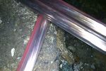
Amdeal 30ft / 10M USB Digital Microscope Cable Wire Endoscope Camera Video Recording Inspection Pipe Camera - Waterproof, 4 LED Lights28 viewsUnder XP system, can watch video directly without install software. By using our software, can take photo,record video, and save the video in the PC. Such USB microscope widely used to inspect tube, check the body, magnify stamps, coins, antiques, insects, electric circuits, machines, fabrics, food, decorations, etc. Please notice that the wire camera is designed for industrial use, not for medical use.
Camera: 1/6" VGA COMS
Pixel: VGA 300K
Resolution: 640x480,352X288,320X240,176X144,160X120
Capture Resolu
|
|
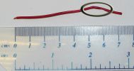
EPB Wire156 viewsThis wire came from somewhere in the EPB circuit and was the cause of my EPB not working. Circled in the picture is the broken part of the wire and just to the right of the break (also within the circle) you can just see a slightly thinner part where the wire has chaffed, removing the insulation.
|
|

Troubleshooting pdf re Mechatronic unit on 6HP26 ZF Automatic 2145 viewsThis 21 page pdf shows possible problems within the Mechatronic unit of the ZF 6HP26 six speed automatic. On page 19/21 is a drawing showing how all the various control circuits interface with the vehicle.
Of particular interest were comments with regards to fine metal contamination of various electrical contacts. This is probably why a mere oil change can improve the operation of the transmission - reduced conductivity of the oil.
|
|
|
|
|
|
|