| Search results - "control" |
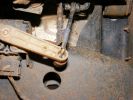
754 viewsNew control rod is carbonfibre/fibreglass hollow tube, with a rubber grommet fitted to one end (screwed and epoxy-ed) and steel rod bent into shape at the other (epoxy-ed).
|
|
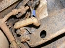
651 viewsNote blue rubber collar to hold lower part of control rod in arm.
|
|
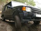
199 viewsSuspension working nicely. Thia model has no difflocks - not to mention electronics - to control wheel spin, so it needed speed to get through some points.
|
|
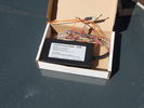
fbh controller7 views
|
|
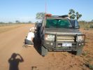
08 D3 stranded with a seized smoking wheel315 viewsAbout 1 hr after replacing the blown tyre, strange noises emanated from the stability control system and speed dropped off. Then I looked in the rear view mirror, and noted a cloud of dust along with a whiff of black smoke. This led to a very quick stop (no traffic on this route for over a week, so no worries about having to signal exiting the road). Took a look and WOW. The right rear wheel was glowing a dull red colour, and burning rubber smoke was wafting from the red glow over the fuel lines.
|
|

Climate control panel removal288 views
|
|
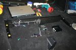
10260 viewsSet up all the controller components in the boot in the unused space available there. The V1000 is ready to be hooked up.
|
|
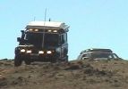
110 at Carinya Escapes ,Flinders ranges295 viewsDefender 110 Extreme,Long Range fuel tank,under floor water tanks, HF radio,GKN Overdrive,Swingaway Spare Carrier,70 litre Freezer,30 litre Fridge,Roof top Camper,Cruise Control,
|
|
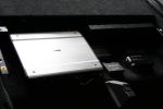
11207 viewsThe controller components are complete and fit neatly within the boot space.
|
|
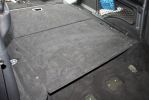
12220 viewsThe boot cover is back in place, hiding away all the controller components.
|
|
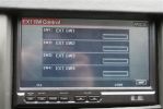
17298 viewsYou can add relay switches to the controller to turn on & off from the touch screen...pretty cool.
|
|
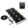
Thread upload9 viewsImage uploaded in new thread
|
|
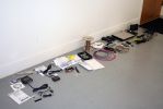
01313 viewsAll the new junk laid out on the floor.
Kenwood KOS-V1000 AV Controller
Kenwood KCA-iP500 iPod Control Interface
Kenwood KOS-L702 Monitor
Kenwood KCA-BT200 Bluetooth interface
Kenwood KNA-G510 Add-on navigation system
|
|
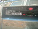
Socket for control lead and switch for radio-remote moved from solenoid pack to bumper1037 views
|
|
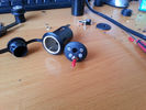
Prototipo height controller miniaturizzato ANITAS 57 views
|
|

+7,5 cm + 5 cm offroad ANITAS height controller by mdm4x4.com metro49 views
|
|
+7,5 cm + 5 cm offroad ANITAS height controller by mdm4x4.com 256 views
|
|
+7,5 cm + 5 cm offroad ANITAS height controller by mdm4x4.com64 views
|
|
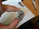
Controller +7,5 cm + 5 cm offroad ANITAS height controller by mdm4x4.com64 views
|
|
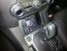
ANITAS D4 suspension module remote controller66 views
|
|
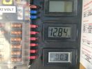
solar controller 48 views
|
|
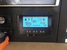
solar controller 60 views
|
|
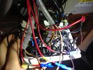
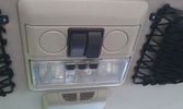
Roof Control panel25 viewsWell.. In reality it does not look as bad.. ;)
|
|
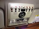
Roof Control Panel33 viewsThe "clean" side
|
|

BOOT Rear Audio controls14 viewsBOOT rear audio wires
|
|

BOOT Rear Audio controls16 viewsBOOT audio wires
|
|

Audio control wiring loom LEFT16 viewsLeft Door wiring loom for audio controls
|
|

Rear left door audio control loom12 viewsRear left door audio control loom
|
|
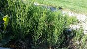
what plant22 viewswant to find out what this plant is and how best to control / remove it from garden
|
|
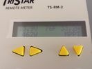
MPPT 45 Tristar 303 viewsThe morningstar Tristar MPPT 45 solar controller.
|
|
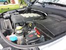
Winch Power upgrade318 viewsUsing 2 warn kits, and removing one of the wires to use on another project. The purpose was to replace the power and ground wire. I used Warn kits, which are 4/0 Welding cable. The original red #4 warped from getting a little too worn. The 2nd
Battery #1 Deka 9A94 AGM Intimidator, Battery #2 Deka 9A47 AGM Intimidator WARN 36080 28" Quick Connect Cable X 2, WARN 26405 Quick Connect Cable 7' X 2, WARN 15901 Black Cable X 1 -- winch control 72" X 1 https://www.facebook.com/DifferentialPartsUS
|
|

Thread upload7 viewsImage uploaded in thread 184680
|
|

Thread upload5 viewsImage uploaded in thread 184680
|
|

Thread upload6 viewsImage uploaded in thread 184680
|
|

Thread upload4 viewsImage uploaded in thread 184680
|
|

Anti Lock and Traction Control description and operation.1987 viewsNote on page 6 of this 17 page pdf the significance of the Steering Angle sensor mounted on the steering wheel shaft. The paragraph regarding the plausibility check as related to the brake pedal being not depressed is why the clean operation of the second set of contacts on the brake switch matters so much.
|
|

Steering Column detailing Steering Angle Sensor1496 viewsItem 2 in the picture on page 1 of the 9 page pdf shows the location of the steering wheel sensor. Page 5 of the pdf has a paragraph describing the operation of the sensor. When the steering wheel does not point the same direction as the real wheels, then the computers can put the 3 into safe mode and down goes the suspension. See also the 17 page pdf on the Anti Lock and Traction Control pdf.
|
|
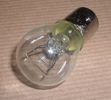
Land Rover Stop Tail Light dual filament bulb nominal 12 volt 21 / 5 watt filaments1427 viewsThis is the Land Rover part number 264590 dual filament bulb, (P21/5), that inserts into the upper two tail lamp receptacles. In the upper one, both filaments function, in the lower one, only the 5 watt tail light filament functions.
I regard it as not a good practice to routinely switch bulbs when the tail light filament, (5 watt), burns out on the lower bulb. The broken filament can jiggle over onto the brake light filament, (21 watt), and short the circuit to ground or something else not predicable.
There are also arguments to say that quality control is better on the Land Rover marketed bulbs than say far east sourced bulbs. Filament construction, and hence resistance can vary and mislead the current sensing circuits monitoring the signal light systems. Also when the bulbs are properly installed, all filaments should be standing vertically and not at any slope.
These are the sort of obscure circumstances that can lead to false trouble messages on the display, dropping to the stops, and subsequent concerns - all over a tail/signal light bulb.
For example, the filament life of both the tail light and the brake light filaments in the P21/5 bulb is significantly less than the USA common 1157 dual filament bulb, (1000/250 vs 5000/1200 hours); brightness in the P21/5 is a bit more, (3cp/35cp vs 3cp/32cp where cp is candle power), but current consumption is oddly less, (0.44a/1.86a vs 0.59a/2.10a where a is amps). It is the quest for efficiency vs maintenance trade off.
|
|

Air suspension Control Module107 viewsDescription: Air suspension Control Module
Location: RH 'A' post
Part No.: YPC500830 Colour: NATURAL Cavities: 20WY
Harness: CABIN HARNESS
|
|

Rear Area Climate Control System1161 viewsThis 14 page pdf describes how the rear heating AC system is supposed to operate in conjunction with the front system.
The air transfer ducts are shown as coloured sketches as is the air flow within the rear blower setup.
|
|

Air Conditioning and Heater Control Components2425 viewsThis is a 21 page pdf that really explains how the air system is supposed to work. Discussed are the exterior ambient air sensor, where and how it operates; the interior temperature sensor as well as humidity sensor.
|
|

Alternator and Regulator Wiring Diagrams, TDV6 and petrol V8 and V61989 viewsThis is a three page pdf that shows the alternator and regulator wiring for the petrol V6, petrol V8 and TDV6. The pdf can be either printed or by right clicking on the displayed pdf, rotated as required for viewing.
Of interest is that the regulator gets its instructions primarily from the Engine Control Module (ECM) and only secondarily from the vehicles electrical buss. The conductor from the battery thru the 5 amp fuse F20E is to provide initial power to excite the alternator at startup and then secondarily, to instruct it if the PWM signals were not available. Primary instructions to and from the ECM are thru the two other conductors via a digital like Pulse Width Modulated (PWM) signal.
If F20E, the 5 amp engine compartment fuse box fuse is blown, the red alternator light on the dash will be illuminated. This means that the alternator could be OK, but if the F20E fuse is blown, no electricity will be generated. Hence check the F20E fuse if you get a red ALT light or some indication of the alternator not working.
Regarding operation of the red ALT light on the dash, it is not the regulator within the alternator that tells the red light to illuminate, or not, but instead the ECM. This is the reason the red light does not function in the same manner as with older vehicles. With the 3, sometimes you have illumination and sometimes not depending upon what the ECM is thinking. What this means is that you can have an alternator that is failing but the red light does not illuminate as the ECM is compensating for reduced alternator output - maybe by draining the battery and or cutting back on vehicle electrical loads such as shutting off or cycling the radio amplifier or heated seats.
|
|

Connector: C2101104 viewsDescription: Rear control valve
Location: Below LH rear wheel arch
Part No.: YPC800230
Colour: BLACK
Cavities: 6WY
|
|

Tools from dealer110 viewsThis is a cel pic of the tools from the dealer for install and removal of control arm bushings. minus one broken tool.
|
|
154 views
|
|

Thread upload36 viewsImage uploaded in thread 92518
|
|

Thread upload17 viewsImage uploaded in thread 187709
|
|

AC Control Components49 views
|
|

44 views
|
|
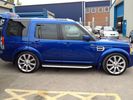
FOR SALE - ONE OFF Land Rover Disco 3 37 viewsOne of a kind Landrover Discovery TDV6 HSE LUX Model 5 door automatic 4x4 diesel evo blue. Upgrades: sidesteps, roof rails, privacy glass, front and rear heated seats/elec seats, landrover tv and headphones, 7 seater black leather, piano black dash/steering wheel, built in fridge, 6 disc changer, sat nav and bluetooth, harman kardon premium entertainment pack, by-xenon adaptive headlights , cruise control and front and rear park distance control, panoramic electric glass roof, 22inch alloy wheels, body kit
|
|
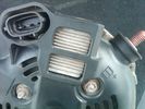
Alternator Plug and B+ terminal919 viewsPictured is the rear of the older Land Rover part # YLE500190 alternator showing the shiny cooling fin of the Regitar VRH2005-142 regulator under.
The first pin in the far left side of the connector is numbered #1 in the LR electrical wiring diagrams and is Battery Voltage Sensing (BVS); the middle pin, #2 receives a Pulse Width Modulated (PWM) signal from the Engine Control Module (ECM), and the right pin, #3 carries a PWM signal back to the ECM. Terminal Pin #2 on the LR wiring diagrams is called Alternator Control or ALT CON; Pin #3 per LR is called Alternator Monitoring or ALT MON.
Pin #1 is similar to what in older designs used to be called A or Batt, but is now called by Denso, S, AS, or Alternator Sensing for this design. Pin #1 also provides power to excite the alternator at startup until the PWM instructions over ride the battery voltage info. Land Rover calls the electronics under the pins a Smart Regulator, ironic, as it has to follow orders from the ECM rather than give the orders - new age thinking I guess. This is different from older design internal regulators that look at just the battery or the electrical buss voltage and then decides itself what to do.
It is almost like we are back to the external regulator designs of old, except that the ECM may decide that instead of telling the alternator to make more power, to load shed, and hence shut down the heated windscreen, seats, or whatever other electrical loads it decides are appropriate. My view is that the "smarts" are in the ECM and that the "regulator" should be regarded if not dumb, then as being a slave to the ECM.
|
|

Altox GSM GPS FBH controller66 views
|
|

Altox WBUS-4 Installation in Discovery 3127 viewsstep by step with pictures how to install the Altox WBUS-4 in the Discovery 3 in footwell
|
|

41 viewsANITAS suspension module D4 MY2012 remote controller
|
|

anti lock control41 views
|
|
The cam with microphone/control buttons180 views
|
|

Aux Climate Control111 views
|
|

auxiliary climate control51 views
|
|

Kenwood v1000 AV-Controller Diagram126 views
|
|
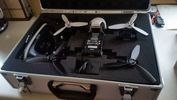
Parrot Bebop 2 Drone in case32 views£30 maplin case for Parrot Bebop 2 and Sky Controller 2
|
|
body control 161 views
|
|
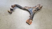
Thread upload17 viewsImage uploaded in new thread
|
|
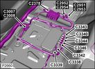
Camera Control Module D451 viewsHarness connection detail, camera module, located beneath L/H passenger side front seat UK D4 spec 2012.
|
|

CAN BUS MESSAGE15 viewsError I get when trying to read the Body Control Module Settings with my MSV2
|
|

climate control43 views
|
|

HVAC Climate Control Wiring Diagram 62 views
|
|
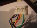
Clock Spring / Rotary Coupler Connector from horn controls209 views
|
|

GoldCruise CM25 stalk mounted cruise controller387 views
|
|
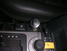
Controller 1147 viewsLocation of HK controller on top of EPB cover.
|
|

Controller 2132 viewsI find that the controller is easier to use when angled forward
|
|
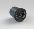
Remote control height controller MDM4x4.com 284 views
|
|
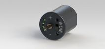
Remote control height controller MDM4x4.com 181 views
|
|
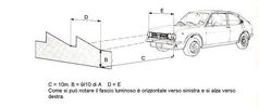
headlight level83 views
|
|
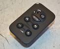
Thread upload16 viewsImage uploaded in thread 159499
|
|
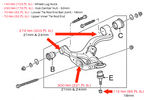
Control Arm label36 views
|
|
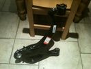
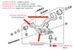
Control Arm RHS42 views
|
|

Control Box61 views
|
|

210 views
|
|
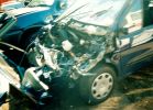
Not much left of bonnet!281 viewsCrash in a Renault Scenic
Head on colition with a Nissan Terrano he lost control came over the central reservation & ended coming at us sideways!
We hit him in the back wheel arch & spun him around so he then hit my drivers side, I walked away having a air bag wife had broken solder coursed by the seat belt, but it did save her life!
Our car was trashed but it did its gob (was only 2 weeks old!) the bonnet tacking lots of energy out of the collision & the inertia staying relatively in tacked.
|
|
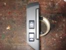
cruise control switch135 views
|
|
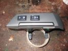
cruise control switch132 views
|
|
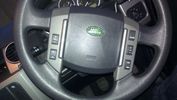
Thread upload16 viewsImage uploaded in thread 104678
|
|
Thread upload16 viewsImage uploaded in thread 172148
|
|
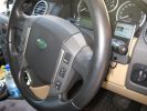
Steering wheel audio controls and iPod dock120 viewsFollowing the instructions I found on Disco3.com.uk it was a breeze the fit the steering wheel audio controls. The iPod dock was a bit more fiddly (took me several hours). Works a treat!
|
|

Steering wheel audio controls and iPod dock103 viewsFitted an iPod dock and steering wheel audio controls. Got then both from Nick at Yeoval Landrover in the UK at a fraction of the price that the Aussie dealer wanted.
|
|

U013224 viewsLost Communication With Ride Level Control Module
|
|

U013225 viewsLost Communication With Ride Level Control Module
|
|

U015535 viewsLost Communication With Instrument Panel Cluster (IPC) Control Module
|
|

U015538 viewsLost Communication With Instrument Panel Cluster (IPC) Control Module
|
|
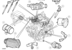
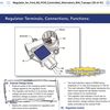
D3_Engine_Control_Sensors_Air_Charge_Temp_Sensor26 views
|
|

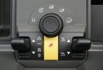
140 viewsHeight controller switch on High (+50mm) setting in my D4
|
|

146 viewsHeight controller switch on Low (-20mm) setting in my D4
|
|

137 viewsHeight controller switch on Medium (+30mm) setting in my D4
|
|

D4 Cruise IID Control18 views
|
|

Auxiliary Climate control53 views
|
|

Aux Climate Control9 views
|
|

HVAC Control Description and Operation10 views
|
|

419-08 Low and High line radio systems components and operation838 viewsThis 15 page pdf displays the radio components including pinouts for both the low and high line head units and the two Harman Kardon amplifiers including the Logic 7 amp. The steering wheel controls for both the radio and phone system are also outlined along with mention of the Sirius satellite radio feature.
|
|
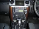
186 views
|
|

Stainless Steel Radio & Heater Control Covers110 views
|
|

Downhill descent control trials81 views
|
|

Italian Maintenance Check Sheet251 viewsLRE008ITA (2)
DISCOVERY 3 SCHEDA DI CONTROLLO MANUTENZIONE (TUTTI I MODELLI INGHILTERRA & EUROPA)
|
|

Italian Maintenance Check Sheet228 viewsLRE011ITA (2)
DISCOVERY 3 SCHEDA DI CONTROLLO MANUTENZIONE (TUTTI I MODELLI PER CONDIZIONI GRAVOSE)
|
|

Italian Maintenance Check Sheet138 viewsJLR 11 81 14_7E (7)
DISCOVERY 3 SCHEDA DI CONTROLLO MANUTENZIONE (TUTTI I MODELLI RESTO DEL MONDO)
|
|
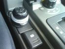
Control Wheel137 views
|
|

63 viewsYou can see how the spot to mount the control box has the long flat section to the left - so I mounted the box upside down to allow the 2-sided tape to stick to this bit.
|
|
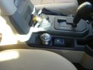
D+P Control Knob in place482 views
|
|
BAS FBH Controller Installed 190 views
|
|
IBS controller190 views
|
|
Rear ventilation controls473 views
|
|
90 viewsRear of car, note control? box just behind and above rear diff
|
|
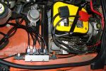
Optima + suspension controler535 views
|
|

Collection279 viewsMe sitting in the D3 just after purchase on 7-6-06, getting to know all the controls!
|
|
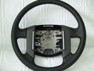
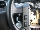
steering wheel c/w horn buttons. No airbag or cruise/audio controls20 views
|
|
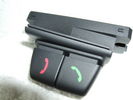
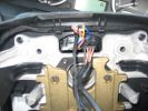
Telephone control fitting for steering wheel28 views
|
|
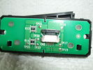
Telephone control fitting for steering wheel ( rear )24 views
|
|
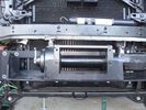
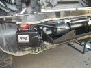
Close-up front view of partially-installed winch121 viewsNote that the sheet-metal flange just above the winch had to be notched to allow winch controller to be actuated. Also this same bracket had to be bent upwards to allow the winch hydraulic:electic solenoid to fit without rubbing. The nut on the upper-left bolt (the one with a very faint circle around it) stripped on re-installation, so the tray and winch pulling load is held only by the threads on 7 bolts....
|
|
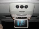
DVD with Air-Con controls185 views
|
|
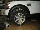
Height controller by marcap599 front max height85 views
|
|
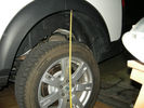
Height controller by marcap599 rear max height77 viewsRear wheel
|
|
Height controller by marcap599 It works!!76 viewsIo e sua altezza competa di corona!
|
|
Height controller by marcap59975 viewsCentral unit beta test
|
|
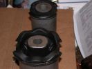
Lower Control Arm Bushings LR3 USA104 viewsLower Control Arm Bushings LR3 USA
|
|

Reversing sensor blackbox controller412 views
|
|
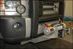
its even got wireless remote controll as well as traditional wired controller192 views
|
|
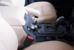
Drive+Play controller146 views
|
|
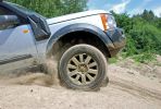
423 viewsCALENDAR ENTRY
Traction Control fighting for life at the top of \'The Hill\' in Tong - but it succeeded!
|
|
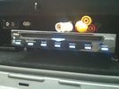
DVD Player63 viewsVeba DVD Player fitted into top glove box, AUX in for connection of Ipod, Games COnsoles etc. Remote control with sensor mounted by rear view mirror.
|
|

29 views
|
|

18 views
|
|

25 views
|
|

24 views
|
|

16 views
|
|

27 views
|
|

electronic engine controls45 views
|
|

Electronic_Engine_Controls.pdf44 views
|
|
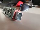
Thread upload4 viewsImage uploaded in new thread
|
|
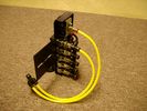
FASKIT on end view 864 viewsEnd and rear view of the FASKIT. Yellow lines are as shipped for hooking to the air supply; one line to valve/filler and other is to gauge. I will modify the arrangement to delete one of the yellow lines such that gauge line plugs into where the second yellow line is right now,(will be only one yellow tube), and then the air source line will plug into the port controlled by the valve, (hidden in this view but visible in other view). When white valve is in the ON position, gauge will read air source pressure, and be available to supply air to any of the selected four air springs. When valve is closed, the gauge will show individual air pressure in each of the air springs when a jumper is run between the gauge Schrader valve and the appropriate air spring Schrader valve.
|
|

Thread upload1 viewsImage uploaded in new thread
|
|
Thread upload1 viewsImage uploaded in new thread
|
|
Thread upload1 viewsImage uploaded in new thread
|
|

FBH Controller - test 121 views
|
|
fbh_controller_v10614 views
|
|

Thread upload0 viewsImage uploaded in new thread
|
|
151 views
|
|
140 views
|
|
146 views
|
|
133 views
|
|
137 views
|
|
137 views
|
|
130 views
|
|
141 views
|
|
132 views
|
|
135 views
|
|
147 views
|
|
143 views
|
|
144 views
|
|
147 views
|
|
144 views
|
|
166 views
|
|
148 views
|
|
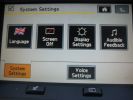
229 views
|
|
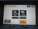
220 views
|
|
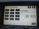
233 views
|
|
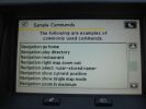
245 views
|
|
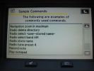
205 views
|
|
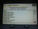
207 views
|
|
237 views
|
|
241 views
|
|
220 views
|
|
212 views
|
|
202 views
|
|

Front control arm clearance738 views275/65/18 Cooper Discoverer STT mud tires - clearance between tire and control arm
|
|

Front_Seat_Control_Switch164 views
|
|

43 views
|
|
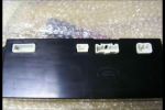
Heater Control Unit Back222 views
|
|
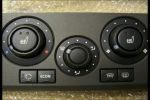
Heater Control Unit Front263 views
|
|
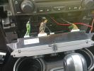
Heater control wiring138 views
|
|
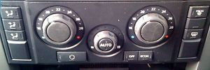
79 views
|
|
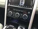
Thread upload7 viewsImage uploaded in new thread
|
|

Thread upload3 viewsImage uploaded in thread 89442
|
|

Thread upload7 viewsImage uploaded in thread 185754
|
|
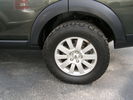
Nitto All Terrain Tires 285/60/1854 views
|
|
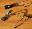
Heated Steering Wheels ECU's97 viewsEarly and Later Heated steering Wheel Control Modules
|
|
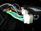
hvac controller124 views
|
|
cable onto controller107 views
|
|
Alternate Buttons Program16 views
|
|

New switch18 viewsNearly 5 years ago, I fiddled with some push-buttons, until one day I came across those marine Contura rocker switches :)
The remote control is the switch just behind the EPB.
|
|

The on/off switch for the middle outlet10 viewsThe left switch without the label is the one that now controls the middle 12V outlet on the second row. It used to be the power on/off of the car-computer.
|
|
The on/off switches of the multimedia headrests17 viewsThese switches were installed to power on/off the previously installed gamecube and the screens attached to it.
When I removed the gamecube and lately the screens as well, I was clever enough (surprised as well) to leave the switches and all the wiring that I had running around.
They came in handy when I installed the multimedia headrests and are now adding an extra power on/off control of the screens.
|
|

60 viewsNormal usage, only the radio's on and controlling the connected iPod.
|
|

An extra twist on running lights30 viewsAdded those nice 120mm LED rings on the covers of the roofrack lights and have them connected to my roofrack lights switch, as I wanted to control the LED manually as well (I don't believe this is 'road-legal', hence why I opted for the manual solution).
|
|
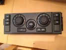
HVAC unit control panel31 views
|
|

Altox FBH controller7 views
|
|
HEIGHT CONTROLLER made in Italy89 views
|
|
-4 cm Height controller D4 by marcap59958 views
|
|

2272 viewsAll back together again, note the connector panel below the heater controls, it has USB and LAN connections for the Onboard PC
|
|
1868 viewsWinch control pack mounted, ready to wire now.
|
|
1634 viewspicture showing the location of the "Lodar" radio winch remote control box.
|
|
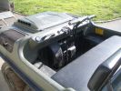
The Controls199 views
|
|
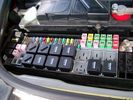
Picture of the engine compartment fuse panel5780 viewsEngine compartment fuse panel located near the battery. This is where F3E, (5 amp), F26E, (20 amp), Fuseable link 10E, (60 amp) and Relay 7E, the now upgraded 70 amp air compressor motor relay, part number YWB500220, (E is for Engine compartment fuse box), are all located. Fuse F35P, (5 amp), is inside the Passenger compartment behind the lower glove box door.
To keep the suspension from going down to the stops when driving, (or parked), it appears that it is only really necessary to remove F26E to depower the exhaust valve and generally keep all the valve block solenoid valves in a closed position trapping whatever air is within the air springs. F3E gets its power thru F26E, so when F26E is removed, the F3E circuit is automatically de-powered. F35P is more interesting in that battery power goes thru the ignition switch and F35P and then into the air suspension control unit. Apparently however, if F26E is removed, removing the F35P is not needed even when the engine is running.
With all fuses still in, if you have a problem, in practice, ideally, the compressor still works and will raise the 3 to an appropriate height. If so, one can then shut the engine off and allow the computers to go to sleep and then you remove the fuse(s). In actual practice, it seems that one need only pull the F26E fuse and can do so with the engine running. All the same, one might consider that the 3 is first a mobile computer, and secondly a 4x4. Computers prefer to go to sleep before the plug is pulled on them, however given that F26E circuit is always alive, then the computer never sleeps. With the fuse(s) pulled, and if you are still up, you can now be a 4x4 instead of a low rider. The whole purpose of the fuse pulling exercise is to depower the one and only system exhaust valve that is physically located within the compressor unit, (to keep it from opening), and secondarily to keep closed the four air spring solenoids within the block valves. This also shuts the air compressor down and stops the air compressor from making air even if the compressor is still good. That is why you initially need the fuse(s) in to allow the compressor to make air if it can.
|
|
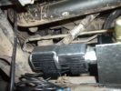
Control Solenoids493 views
|
|
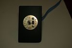
Controller centralina ANITAS D321 views
|
|
Controller centralina ANITAS D3 bis22 views
|
|

First module - FBH Controller 22 views
|
|

463 viewsPrevious installation.
Only my GPS, Mobile and MP3 changer in the back (controller seen on later pictures)
|
|

473 views@ home, we have 2 remote controlled garage doors. So I installed the remote controller in the car, added 2 buttons and off we go. Lucky me the controller worked at 12V anyway :D
I'll add a LED onto that one, so I'm sure it works when I press :)
|
|

533 viewsAdded an extra switch to the + leading to my PC and to the MP3 changer. As such I can cut off the power to both systems when needed. Learned that one after 2 days constantly working in the car, lighting the whole thing up during 2 days and noticed I couldn't start anymore :D. Saved by my wife's Freelander next to me :)
Also to be seen is the remote controller of the MP3-changer.
|
|

419 viewsSwitch in up position, bright controller. I love the blue. A pitty all the other displays in the car are in green.
|
|

BD/C82D114 viewsDual Controls 66L, Others
https://www.facebook.com/snomasterusa
|
|
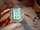
Missing pin38 viewsControl board from EPB
|
|

Fridge Controls208 viewsSnomaster 72 Fridge controls. https://www.facebook.com/DifferentialPartsUS
|
|

122 views72L Portable Fridge Freezer Controls
https://www.facebook.com/snomasterusa
|
|
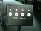
Camera controller43 views
|
|
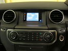
D4 Lowest Grade Radio - Wide Angle76 viewsThe CD player is at the bottom of the picture, the control buttons in the middle, and at the top is the screen with colour-lit icons on the left to indicate source, and bluetooth icon on the right to indicate connectivity. There are also two hardware buttons for hour/minute clock setting.
|
|
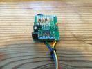
tobouk FBH controller14 views
|
|
Cabled winch control connector114 viewsAdditional angle bracket made for connector in aluminium attached to red grill. Additional in-line connector between this and the solenoids to allow rad grill to be removed when required.
|
|

D4 height controller switch location37 views
|
|

D4 height controller switch location 253 views
|
|

Transfer case control module31 views
|
|

Fitted Control Switch192 views
|
|
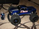
32 viewsNew Christmas toy to try to learn the finer points of speed control over obstacles... Now I just need an LR3 body that will fit this monster...
|
|

FBH Controller - Scale Photo - A424 views
|
|
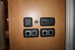
Heating, Power and Water controls32 views
|
|
This is the controller unit that I attached to the emergency brake pop-out plate.386 views
|
|

This is a night photo of the completed installation. The controller and screen brightness can be adjusted.499 views
|
|
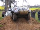
246 viewsNo traction control was getting me out of this one!
|
|
Thread upload2 viewsImage uploaded in new thread
|
|

128 viewsWiring Diagram for HEVAC-System
|
|
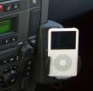
iPod cradle235 viewsThe dealer used the phone fitting and the iPod was installed via cinch connectors. Volume is controlled via the audio, charging function also included.
The sound even with the basic Audio system is terrific!!!
|
|

Kenwood v1000 AV-Controller Install Diagrams132 views
|
|

L319_MK4_ALTOX_GSM_remote_control_installation_manual39 views
|
|

LA100-005 - Technical Bulletin - Internal Control Module Faults Relating to the ABS Module Diagnosis84 views
|
|

LA501-021 - Technical Bulletin - Restraints Control Module Diagnostic Trouble Codes73 views
|
|
43 views
|
|
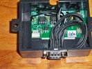
Controller Box152 views
|
|

LR Electric Trailer Brake C2590 Female Connector606 viewsThis female connector, C2590, located up above and near the brake pedal is for the Trailer Electric Brake Controller hookup.
The Black wire in the bottom right is pin #3, the ground. The Blue wire to the left is pin #6, the Trailer Brake Controller output going to the rear trailer socket.
The White #4 wire is the 30 amp fusible link, (Link 6E in the engine compartment junction box), for the Brake Controller 12VDC power feed from the battery. Note that this would make a pretty good power source for CB radios and the like if no electric trailer brakes were required.
Pin #5 is a Green wire from the stop lamp switch, (the control input for the Brake Controller).
This plug is standard on all NAS (LR3) vehicles, but unlikely to be found on the D3 spec units.
|
|
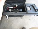
414 viewsHere is the left rear cubby box with the TM-D700A bolted inside. I also drilled a hole in the bottom of the cubby for antenna, GPS, and power wiring, and a hole in the front for control, microphone, data, and audio cabling.
|
|
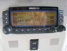
461 viewsCompleted install of control panel.
|
|
388 viewsCompleted Install of Control Panel. Wiring goes up into headliner, over curtain airbag on left hand side, and down the B pillar.
|
|
Air Suspension ECU Fuse 35P Shut Off Switch2635 viewsA more distant view of the shut off rocker switch in the ON position which is the normal position for when all is working as Land Rover intended.
Ideally, (but not totally necessary), the F35P circuit should be powered or de-energized after the various computers have gone to "sleep".
Similarly, removal of the F26E or F3E fuses is preferable after the computers have all gone to sleep but it appears that no real damage will be done if the fuses are removed while the system is energized. Pulling F26E is the main full time fuse that powers the air suspension computer. As such, once F26E is removed, pulling F3E is not really required.
Power for the compressor goes thru the 60 amp fusible link and relay, however control of the relay is via the air suspension computer so depowering the air suspension computer effectively depowers the air compressor and the internal exhaust valve relay/port.
|
|
Compressor Electrical Plugs 1406 viewsThis shows the two electrical connectors; the two pronger is the power to the compressor, and the multi-pin connector carries control signals. Also the temporary red plug is where the 6 mm tubing from the centre valve block connects. This line carries both the compressor and exhaust air to and from the springs.
|
|
View from front left side looking towards rear aux battery compartment under cover 647 viewsAs there is no Fuel Burning Heater in the NAS V8 petrol vehicles, there is space available to install the FASKIT panel here. The piping is such that each air spring can be isolated from the air system and then filled one at a time manually via the Schrader valve. There are five Schrader valves and five shutoff valves. The fifth valve nearest the gauge controls air from the compressor, and can provide fill up air via a jumper fill line assuming the compressor is still operational.
|
|
Wiring, (tubing), loom exiting temporarily from the front right fog light.569 viewsThe front axle air valve block is located just behind and below the fog light. Access to the valve block is by removing the right front fender liner, (or the bumper). The FASKIT lines are attached to the left and right front air spring lines at this location; also compressor air is taken from this location as well. Cutting the lines at as few different locations makes it easier to find leaks at a later date. As above, five 6mm air lines run from the FASKIT panel to the front axle air valve assembly and run within the loom. Two pair of the lines are for control of the air springs, and the fifth line taps the air supply at the valve block assembly off the compressor. This will be the air source line rather than tapping in directly to the high pressure air tank.
|
|
Thread upload12 viewsImage uploaded in thread 86153
|
|

Thread upload15 viewsImage uploaded in new thread
|
|
Thread upload15 viewsImage uploaded in thread 86153
|
|

LR3 Denso Alternator YLE500390 pulley view819 viewsNote the DENSO sticker on the side. Denso calls their nominal 150 amp 12 Volt alternator an SC2 design. SC means Segment Conductor which apparently increase the winding density of the stator coil, hence yielding a physically smaller lighter alternator for a given output. I presume the 2 means the second try at getting it right. A Denso part number is 4280003690 for the alternator, (there are others, as below).
Rotation is clockwise and the 54mm diameter pulley has 6 grooves (PV6x54). Count the pulley grooves on both the one you remove and your new one - some replacement alternators seem to ship with 5 or 7 grooves so you might be swapping pulleys.
A previous LR part number was YLE500190 for the older variation of the newer YLE500390 unit.
An additional part number for a factory rebuilt is Nippon Denso 210-0569 for the petrol V8 alternator. Other Nippon Denso numbers include 104210-3690 and 104210-3691. The Lester number is 11206 which relates to another Denso number of 290-5287. WAI uses 11206N.
From 2006 to 2009, the internal regulator is a Transpo IN6349 and of the B circuit type if it can be said that applies to PWM, (Pulse Width Modulated), regulators.
The "regulator" inside the alternator is therefore really not a regulator in the old sense of the term but instead an instruction receiver from the ECM that translates Pulse Width Modulated (PWM) signals into a form that the alternator understands – digital like signals from the Engine Control Module(ECM) into analogue like signals that the windings understand.
|
|
97 views
|
|

Engine and Transmission Electronic Controls Wiring Diagram996 viewsThis 20 page pdf shows the wiring for the electronic controls for the engine, transmission and transfer case.
|
|

Stop Light Lamp Circuit pdf2491 viewsThis pdf shows the brake light circuit for the NAS LR3.
Note that power for the brake light bulbs can come either thru the brake light switch power feed /contacts plus also from the Hill Decent Control, (HDC), system relay located within the Central Junction Box, (CJB) - yes two separate sources of power for the brake light bulbs. This would tend to explain how a brake light circuit concern shows up as a hill decent fault message; also why lesser vehicles without hill decent braking mechanisms, (HDC), never display this sort problem when a brake light bulb or switch acts up. You never have a problem related to a system that does not exist.
Additional evidence of the relationship of the HDC and the tail light circuit is demonstrated by when the HDC actually acts to slow the 3 down, the brake lights automatically illuminate even if the slowing action was merely retarding the engine speed or shifting to a lower gear, (in other words, no foot on the brake pedal).
There is also a tie in to the Cruise Control and hence a failing brake light switch can affect cruise operation or just create false Cruise Control messages. To further complicate the issue, while there are no messages generated, operation of the radiator electro viscous fan can also be negatively affected by the fouled set of secondary contacts within the brake light switch. This is all because the NC contacts within the brake switch send misleading messages to the ECU.
While the ground wire design is similar to other vehicles, note the grounds for the brake light filament and the reverse light filament are common on each side. That means that if one has a non functioning brake light on one side, the reverse light may not also work or that some problem with the reverse lights could back feed into the brake lights. This situation while unusual, can result when grounds are corroded probably due to swimming in rivers and creeks or just routine driving in a marine environment.
|
|

Thread upload15 viewsImage uploaded in thread 167285
|
|
Thread upload3 viewsImage uploaded in thread 155707
|
|

LTB00321 - Technical Bulletin - Restraints Control Module Diagnostic Trouble Codes114 views
|
|

Thread upload12 viewsImage uploaded in thread 89026
|
|
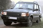
First Discovery10 viewsA battered-to-death-by-farmers and then brought-back-from-the-dead 300TDi Disco. When first seen the driver's seat was a plastic crate. Resprayed in Eastnor Green with replacement front seats and steering column controls that had been chewed off by farmer's dog. In many respects my best Land Rover buy ever!
|
|

NAS 7 plus 4 pin LR3 Trailer wiring, battery end. 549 viewsThis is the LR wiring diagram from the engine compartment battery location to the Electric Brake Controller connector, C2590, located under the dash near the brake pedal.
|
|

NAS 7 plus 4 pin LR3 Trailer wiring, trailer end. 498 viewsThis is the LR wiring diagram showing the conductors from the the Trailer Brake Controller connector, C2590, back to the rear combo NAS 7 plus 4 pin sockets.
|
|
separate vol control for direction voice33 viewsthere are many voice options one of which is a chinese donald duck ..no really thats what its called
|
|
Nokia CK-7W with bluetooth control681 views
|
|

Thread upload1 viewsImage uploaded in thread 154757
|
|

Thread upload0 viewsImage uploaded in thread 89442
|
|
Thread upload2 viewsImage uploaded in new thread
|
|
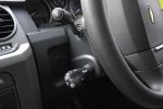
Goldcruise control showing presets, fitted to LHD key blank484 views
|
|

Thread upload1 viewsImage uploaded in new thread
|
|
caravan fridge controls8 views
|
|
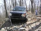
some of the gates were very narrow432 viewsThe LR3's tight turning radius was a great help. You are only allowed one shunt (backup) per course section, so it is best to save it for when you really need it. I was very impressed with how slowly the LR3 can walk over the rocks, I had it set to rock crawl, and used either 1st or 2nd gear, depending on the terrain and size of rocks. mostly used 2nd, it give better throttle control.
|
|
Coming out of an small off-camber ravine472 viewscoming out of an off camber ravine and lining up for the next gate. The LR3's traction control was great, even with the stock tires there was virtually no slipping.
|
|
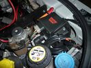
warn winch controller installation613 viewsremotely installed due to space limitations, and to keep the unit dry. Left Hand Drive, fitted in engine bay near washer fluid fill for reference point.
|
|
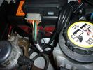
warn winch controller installation544 viewsremotely installed due to space limitations, and to keep the unit dry. Left Hand Drive, fitted in engine bay near washer fluid fill for reference point.
|
|
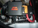
warn winch controller installation568 viewsLeft Hand Drive, fitted in engine bay near washer fluid fill for reference point.Remote control unit fitted on the box. Remotely installed due to space limitations, and to keep the unit dry.
https://www.facebook.com/DifferentialPartsUS
|
|
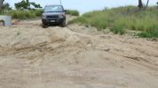
Fingal Road - Northern end187 viewsOnly sand driving we did was on this well packed and still damp sand leading to the sand pumping station (used for erosion control). Didn't even need to select Sand mode from the terrain tamer although I did put it in Extended Mode just in case.
|
|
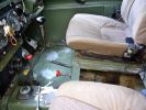
Horizontal red lever is the PTO engagement control.151 views
|
|
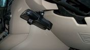
P3 brake controller 198 views
|
|
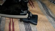
P3 brake controller mount 288 views
|
|
P3 brake controller mount 384 views
|
|

Parking control Work shop manual16 views
|
|

14 views
|
|
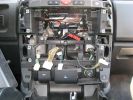
261 viewsPicture of the center console minus IHU and Climate Control. Turns out there is very little room behind there, which is really a pain in the ass.
|
|
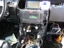
257 viewsSystem testing. Nothing caught fire, which is a success in my book! Just know that the rover gets very angry when all of those control panels are disconnected.
|
|
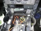
255 viewsThe console mostly re-assembled. You can see the dremel notch I made for the control cables, as well as the slack in the power and audio cables.
|
|
329 viewsInstallation slowly proceeding. You can see the controller cables inserted into the notch I made with a dremel.
|
|
255 viewsAlmost completed install. Just the controllers need mounting.
|
|
246 viewsAlmost done. All the trim is in, but the controllers are not yet mounted.
|
|
307 viewsCompleted install. I used a bar of aluminum bar with 3M industrial velcro to hold the controllers.
|
|
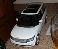
Remote Control Full Fat Range Rover25 views
|
|

Rear Climate Control249 views
|
|
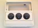
rear_aircon_control33 views
|
|

Rear32 views
|
|

Transpo pdf explaining the operation of Ford PWM regulators624 viewsThe 4 page pdf produced by WAI-Transpo explains the operation of the Pulse Width Modulated regulators located within the alternators on our 3's. Of note, the pdf states that certain of the Ford PWM regulators do not meet Ford spec.
The pdf explains the function of all the terminals and the apparent advantages of the PWM style over previous designs. Note that Ford calls their "engine computer" a PCM, (Power Control Module), whereas Land Rover, an ECM, (Engine Control Module).
|
|

Discovery 2 Remote Suspension Control105 views
|
|

Rosen Owners Manual894 viewsThis 28 page Owners Manual is the Rosen version written specifically for the A10 model DVD Video Game Entertainment System player that may in attached to the roof of your 3.
Discussed is how to use the remote control, the wireless headphones, the TV feature if installed, and how to change from 16:9 widescreen format back to the older 4:3 format.
|
|
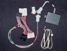
Electronic height controller trial kit251 viewsElectronic height controller kit incl trial extension looms & dummy plug
|
|
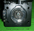
NAS 7 pin + NAS 4 pin Flat Trailer Socket308 viewsThis is the vehicle end of the NAS trailer harness that is located behind the removable plate centered within the rear bumper by the towing loop. Re the four pin flat connector, from the bottom, the exposed bare lower pin is the ground, usually the White wire on a NAS trailer. The next pin up is normally a Brown wire on a trailer and is for the Tail Lights. The third pin, normally a Yellow wire, is the left signal light; the top pin, normally a Green coloured wire, is the right signal light.
Re the round connector, from the notch in the plastic surround, clockwise, the first blade is ignition controlled +12VDC battery power, (only alive when engine running), and on the Land Rover factory harness is an Orange wire; on a NAS trailer, usually Red but perhaps a Black wire.
Next blade clockwise at 3:00 o'clock above, is the Right Turn signal light, a Green wire on the LR harness, and also on a NAS trailer.
At 5:00 o'clock, the next blade is for the Electric Brakes and is Blue on both the LR harness and on a NAS trailer.
The Ground wire is next, White on both the LR harness and on a trailer.
At 9:00 o'clock above, is the Left Turn signal, Yellow on both the LR harness and on a trailer.
The last blade to the left of the line up notch is the Tail Light circuit. On the LR harness, the wire colour is Brown with two White stripes and on a NAS trailer, Brown.
The centre pin is for the Reverse Back Up lights and is Black on the LR harness and often Purple on NAS trailer wiring but can be Black also.
Note that when the socket assembly is installed on the 3, the notch in the plastic surround is on the left - that is rotated 90 degrees anticlockwise to the picture above. In other words, When installed on the 3, the 4 pin flat connector lays horizontal and is located below the round socket.
|
|
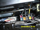
97 viewsConnectors under my driver seat..
Right connector for Heated seat + airbag ++
Left connector for Seat controll I hink
|
|
Rear Ac control connector_0133 views
|
|
Rear Ac control connector32 views
|
|
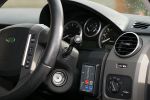
IBS Split Charge controller132 views
|
|
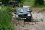
Traction control in full operation430 views
|
|

Thread upload9 viewsImage uploaded in thread 196629
|
|
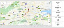
Thread upload34 viewsImage uploaded in thread 198923
|
|

Thread upload11 viewsImage uploaded in new thread
|
|

Thread upload9 viewsImage uploaded in thread 174440
|
|

Thread upload9 viewsImage uploaded in thread 173730
|
|

Thread upload8 viewsImage uploaded in thread 173730
|
|

Thread upload9 viewsImage uploaded in thread 173730
|
|

Thread upload7 viewsImage uploaded in thread 173730
|
|

Thread upload8 viewsImage uploaded in thread 173730
|
|

Thread upload9 viewsImage uploaded in thread 173730
|
|
![Filename=Screenshot_20180903-163921_IIDControl[1671].jpg
Filesize=49KB
Dimensions=622x1279
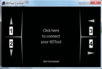
Date added=03.Sep 2018 Screenshot_20180903-163921_IIDControl[1671].jpg](albums/userpics/42967/thumb_Screenshot_20180903-163921_IIDControl%5B1671%5D.jpg)
Thread upload9 viewsImage uploaded in thread 174742
|
|

Thread upload5 viewsImage uploaded in thread 175076
|
|

Thread upload4 viewsImage uploaded in thread 175076
|
|

Thread upload6 viewsImage uploaded in thread 175076
|
|

Thread upload7 viewsImage uploaded in thread 175076
|
|
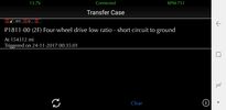
Thread upload0 viewsImage uploaded in new thread
|
|

Thread upload0 viewsImage uploaded in new thread
|
|

Thread upload0 viewsImage uploaded in new thread
|
|

Thread upload0 viewsImage uploaded in new thread
|
|

Thread upload0 viewsImage uploaded in new thread
|
|

Thread upload1 viewsImage uploaded in new thread
|
|

Thread upload0 viewsImage uploaded in new thread
|
|

Thread upload0 viewsImage uploaded in new thread
|
|

Thread upload5 viewsImage uploaded in new thread
|
|

Thread upload0 viewsImage uploaded in thread 180839
|
|

Thread upload1 viewsImage uploaded in new thread
|
|

Thread upload3 viewsImage uploaded in new thread
|
|

Thread upload4 viewsImage uploaded in new thread
|
|

Thread upload2 viewsImage uploaded in new thread
|
|

Thread upload3 viewsImage uploaded in thread 185537
|
|

Thread upload8 viewsImage uploaded in new thread
|
|
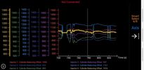
Thread upload15 viewsImage uploaded in new thread
|
|

Thread upload2 viewsImage uploaded in new thread
|
|

Thread upload2 viewsImage uploaded in new thread
|
|

Thread upload12 viewsImage uploaded in new thread
|
|
Thread upload14 viewsImage uploaded in thread 187315
|
|

Thread upload15 viewsImage uploaded in thread 187315
|
|

Thread upload2 viewsImage uploaded in new thread
|
|

Thread upload14 viewsImage uploaded in thread 187315
|
|

Thread upload5 viewsImage uploaded in new thread
|
|

Thread upload5 viewsImage uploaded in thread 169982
|
|

Thread upload2 viewsImage uploaded in thread 189767
|
|

Thread upload11 viewsImage uploaded in thread 126044
|
|

Thread upload3 viewsImage uploaded in thread 190931
|
|
Thread upload0 viewsImage uploaded in new thread
|
|
Thread upload0 viewsImage uploaded in new thread
|
|
Thread upload0 viewsImage uploaded in new thread
|
|

Thread upload3 viewsImage uploaded in thread 190931
|
|

Thread upload3 viewsImage uploaded in thread 190931
|
|

Thread upload4 viewsImage uploaded in thread 190931
|
|

Thread upload3 viewsImage uploaded in thread 190931
|
|

Thread upload4 viewsImage uploaded in thread 190931
|
|

Thread upload5 viewsImage uploaded in thread 190931
|
|

Thread upload3 viewsImage uploaded in thread 190931
|
|

Thread upload4 viewsImage uploaded in thread 190931
|
|

Thread upload6 viewsImage uploaded in thread 190931
|
|

Thread upload4 viewsImage uploaded in thread 190931
|
|

Thread upload6 viewsImage uploaded in thread 190931
|
|

Thread upload5 viewsImage uploaded in thread 190931
|
|

Thread upload3 viewsImage uploaded in thread 190931
|
|

Thread upload7 viewsImage uploaded in thread 190931
|
|

Thread upload4 viewsImage uploaded in thread 190931
|
|

Thread upload4 viewsImage uploaded in thread 190931
|
|

Thread upload1 viewsImage uploaded in thread 191700
|
|

Thread upload1 viewsImage uploaded in thread 191700
|
|

Thread upload1 viewsImage uploaded in thread 191700
|
|

Thread upload1 viewsImage uploaded in thread 191700
|
|

Thread upload2 viewsImage uploaded in thread 191958
|
|

Thread upload3 viewsImage uploaded in thread 191958
|
|

Thread upload1 viewsImage uploaded in thread 154757
|
|

Thread upload11 viewsImage uploaded in thread 193063
|
|

Thread upload1 viewsImage uploaded in thread 154757
|
|

Thread upload4 viewsImage uploaded in thread 154757
|
|

Thread upload2 viewsImage uploaded in thread 194182
|
|

Thread upload4 viewsImage uploaded in thread 194182
|
|

Thread upload1 viewsImage uploaded in new thread
|
|
Thread upload4 viewsImage uploaded in new thread
|
|
Thread upload3 viewsImage uploaded in new thread
|
|
Thread upload3 viewsImage uploaded in new thread
|
|
Thread upload1 viewsImage uploaded in thread 194659
|
|

Thread upload8 viewsImage uploaded in new thread
|
|

Thread upload4 viewsImage uploaded in new thread
|
|

Thread upload4 viewsImage uploaded in new thread
|
|

Thread upload1 viewsImage uploaded in new thread
|
|

Thread upload4 viewsImage uploaded in new thread
|
|

Thread upload3 viewsImage uploaded in new thread
|
|

Thread upload2 viewsImage uploaded in new thread
|
|

Thread upload2 viewsImage uploaded in new thread
|
|

Thread upload3 viewsImage uploaded in thread 196024
|
|

Thread upload0 viewsImage uploaded in thread 196024
|
|

Thread upload2 viewsImage uploaded in thread 196024
|
|

Thread upload3 viewsImage uploaded in thread 196024
|
|

Thread upload3 viewsImage uploaded in thread 196024
|
|

Thread upload8 viewsImage uploaded in thread 197165
|
|

Thread upload1 viewsImage uploaded in new thread
|
|

Thread upload0 viewsImage uploaded in thread 198311
|
|

Thread upload1 viewsImage uploaded in thread 198311
|
|

Thread upload0 viewsImage uploaded in thread 198311
|
|

Thread upload0 viewsImage uploaded in thread 198311
|
|

Thread upload1 viewsImage uploaded in thread 198311
|
|

Thread upload1 viewsImage uploaded in thread 198311
|
|
| 513 files on 2 page(s) |
 |
1 |  |
|