| Search results - "how" |

0000 LR Bluetooth dealer Kit install instructions1611 viewsThis 17 page pdf is mostly a series of pictures showing how to install the original Land Rover dealer installed Bluetooth kit for circa 2005 / 2006 three's. Also included are three wiring diagrams sheets related to the pairing code 0000 Bluetooth install.
This pdf is useful if you are now removing the 0000 kit to install the optical 2121 MOST D4 module, an easier install than the 0000 kit ever was.
|
|
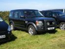
My Disco 3 at the Camelford Show124 views
|
|
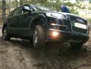
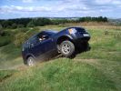
205 viewsQ7 working hard. note how little the suspensipon works. But - never got stuck!
|
|
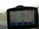
How fast?231 viewsI was driving along the Autobahn, glanced down at the speedo which was showing 140 mph, the Tomtom was telling the truth at 132 mph, but by the time I had switched the phone to camera I had dropped 2 mph, didnt try and do it again as there was no need.
|
|
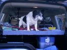
168 viewsthis is Albert 15 years old, showing the virtues of travelling club class, in the rear of a disco 3
|
|
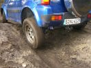
188 viewsJimny. Note how well the suspension works.
|
|
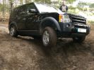
249 viewsMy baby showing off it´s air suspension :)
|
|

Silverstone Classic Media Day177 viewsAttended the media day for the Silverstone Classic, took 3 cars to display & tell 300 journalists what we do at the show.
David Coultard was one of the drivers who were taking the journalists around the track.
|
|
122 viewsshows the height of both adapters
|
|
115 viewsside by side shows the larger one adapted at the base
|
|

Photo showing bend required in hook105 views
|
|
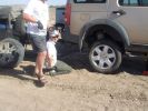
06 Spare tyre on and still suffering from hot wheel nuts296 viewsManaged to get ultra hot wheel nuts back on the spare (using the original 19" D3 wheel, vs the 19" RRS wider wheel which blew - shown in left of photo). Pity we didn\'t note that the disk brake was EXTREMELY hot at this time.
|
|
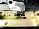
Lavoro finito - Finished work39 viewsEcco come appare a lavoro finito
Here is how it looks, finished the job
|
|
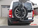
This is how to make it all work. Backup sensor on carrier43 viewsHighlift, ax and shovel. Yes they are matching colors. What else?
|
|

09 Starting to remove the seized brake assembly296 viewsBy this time we\'d poured about 8l of water on the dull-red glowing and burning wheel assembly (too close to 140l of 98 octane petrol). Sudden cooling cracked the disk brake which showed mangled park brake parts. How to remove a brake disk without the right star fitting? First remove the caliper then get a sledge hammer?!!
|
|

10 Cracked smoking parking brake drum338 viewsNote the crack in the face of the brake. This showed mangled parking brake springs and other bits. Also a bit of melted rubber was drooling out of the crack. Started to remove the brake caliper and enjoying the flies in 45 deg C heat. Ah, the wonderful Aussie climate in January.
|
|
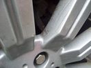
whole wheel33 viewsShowing cracks on the other 3 wheels which didnt quite fail
|
|
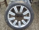
Front View35 viewsShowing the wheel which failed whilst driving.
|
|
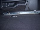
Side runner in position showing front lower than rear.33 views45%
|
|
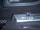
Close up of side runner, showing load hooks countersunk into runner .24 views50%
|
|
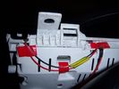
Insrument panel rear 34 viewsShowing wiring for heater and lights on indicator
|
|
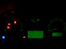
Insrument panel 36 viewsShowing heater and lights on indicator
|
|
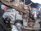
252 viewsThe old belt with rubber crumbs showing
|
|

12 Half way through removing a jammed disk brake in the Outback297 viewsThis was just before breaking the sledge hammer. Note we luckily carried a spare hammer. Ended up using (or breaking) every tool we had on this little repair job. Bed sheets are a good way of gathering the bits to show for the inevitable warranty claim.
|
|

Finito - At the end47 viewsEcco come appare la sponda a lavoro finito.
Here is how is the job ended.
|
|
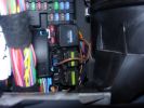
Permanent 12V supply271 viewsPhoto taken of TFC\'s D3 showing where you can take a permanent +12V supply, from the main fuse board behind the glove box.
|
|
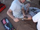
13 How to care for tools303 viewsWhat happened to the sledge hammer after 2 hours of beating my seized and cracked disk/park brake assembly to bits. Now down to 1 hammer remaining. At least by this time it was getting cooler (down to 40 deg C)
|
|
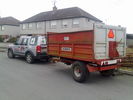
honestly officer....if it was overloaded, it would be sitting on the rear axel ??? heh heh79 viewsfunny how some cops will accept what their eyes tell must be the truth, a trailer load of logs home ....easy peasy, hahahahaha
|
|

Thread upload24 viewsImage uploaded in new thread
|
|

15-20200928_Vigor166_DSL_Stats_G_fast_Showtime12 views
|
|
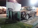
The obstacle...14 viewsThis what we had to push. You cannot believe how heavy this is. It looked easy, but let me tell you, I have seen many groups of 3 young tough guys curse and sweat...
|
|
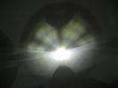
This is a normal H7 HID bulb installed in a BMW headlight to show glare above cut off line99 viewsThis is what the light pattern is that causes glare in most retofit applications including some projector lights. this is in fact a projector headlight on a BMW but the old projectors were only actually half projectors and half reflective bowls. the beam pattern should be clean cut like this ___/
|
|
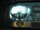
H7R Headlight retrofit H7R HIDS4U notice no light in bottome half of the bowl98 viewsThis is how a retofit HID should look in a reflector headlight
|
|
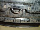
Rivetted in bracket, showing tabs that will be sandwiched by the plate95 views
|
|
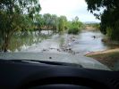
D3 in the Mary River Flood plains47 viewsIn this part of the world, on the flood plains out to Kakadu, you never get out to wade a creek first as the theory says you should. If the water isn\'t clear, like it was on this causeway, and it is this wide, you either wait for someone else who is braver than you to cross first, or you turn around and go home. These rivers are full of estuarine (salt-water) crocodiles, and they are starting to reach 7 metres in size in some still rare instances. However, seeing as a 2.5m crocodile can kill a grown man,
|
|
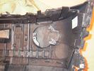
Back of bumper shows pre-fitted fog lamp brackets988 views
|
|

FFRR66 views
|
|
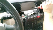
yes, i am cutting it...26 views
|
|
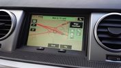
Proof of updated map data23 viewsPostal code CH4 0FB
Showing roundabouts where on current LR DVD are none.
|
|
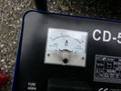
Amps43 viewsThis picture shows how mutch my disco uses while programing the engine management ecu
|
|

what plant22 viewswant to find out what this plant is and how best to control / remove it from garden
|
|

16 viewsShower area
|
|
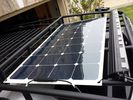
solar roof install444 viewsMore or less wrapped up my solar installation today. I added a Grape Solar Flex 100W panel, it's adequate to keep the vehicle topped off with the Fridge running, and Ham, but it could lose some ground if transmitting depending on how much, 2 would be awesome. One is enough, but barely. I am quite impressed with the Grape Solar flex panel version 2.0.
https://www.facebook.com/DifferentialPartsUS
|
|
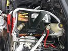
Wiring342 viewsThis is the final wiring configuration. It shows the dual battery wiring, 75A wiring run to the boot, the winch and in the lower right you can see a few turns of coax with a snap on ferrite near the base of a VHF Antenna.
|
|

Steering Column detailing Steering Angle Sensor1497 viewsItem 2 in the picture on page 1 of the 9 page pdf shows the location of the steering wheel sensor. Page 5 of the pdf has a paragraph describing the operation of the sensor. When the steering wheel does not point the same direction as the real wheels, then the computers can put the 3 into safe mode and down goes the suspension. See also the 17 page pdf on the Anti Lock and Traction Control pdf.
|
|
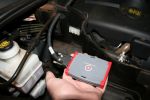
TT Box Size125 viewsSize of the new TT box shown in my hand
|
|
This road isnt on a bus route!124 viewsWent to see how my new house is looking in Czech Republic, this is one of two roads out of the village
|
|
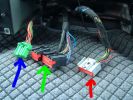
28 Dash Loom50 views
|
|
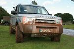
Stoneleigh show54 views
|
|
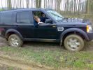
Well and truly stuck on a green lane at the weekend, there was a hill that does not show up in the photo!273 views
|
|
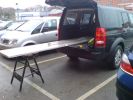
292 viewsNeeded 1.8m of worktop but had to buy 3m length. Took B&D workmate with me and cut it down to size in the car park! Notice how the workmate is exactly level with D3 in normal height!
|
|

Thread upload1 viewsImage uploaded in thread 186251
|
|

Engine Accessory Drive Description and Operation884 viewsThis 2 page pdf shows both belts for the 4.4L petrol V8; the primary serpentine belt, (the long one), and the shorter secondary that drives only the radiator cooling fan.
The various accessory pulleys the two belts are each associated with are numbered and an included table describes each.
When replacing belts and pulleys, count the number of grooves on both your old items and your new replacement parts. It has been known for an pulley with the wrong number of grooves to come with a replacement part or the replacement belt has the incorrect number of grooves; hence make certain the groove count on the new parts are the same as the removed items.
|
|
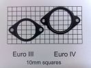
Photo of Euro III and Euro IV plates to show difference127 views
|
|
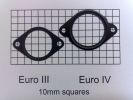
Photo of Euro III and Euro IV plates to show difference145 views
|
|

3 Point Hitch on Series 90152 viewsUsually one sees the Series units with just a conventional field plow hooked to a drawbar hitch, tractor style. This jpg however is the full meal deal - a 3 point hitch, probably off a Fordson tractor, in the long tradition of Ford/Land Rover cooperation.
|
|
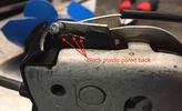
Close-up of lock showing emergency cable and pared back plastic tab141 views
|
|

Front Heater Doors Description and Operation1396 viewsThis 6 page pdf shows with coloured drawings the air flow thru the front heater as well as discusses the operation of the various air flow doors.
|
|

Air Conditioner Specifications 4.4L V81570 viewsThis 2 page pdf is just the specifications for the AC system. The refrigerant type is R134A.
Note that when topping the system up, it can be a good idea to include some of that ultra violet light dye that will glow to show leaks and loose fitting.
|
|

Rear Area Climate Control System1161 viewsThis 14 page pdf describes how the rear heating AC system is supposed to operate in conjunction with the front system.
The air transfer ducts are shown as coloured sketches as is the air flow within the rear blower setup.
|
|

Air Conditioning and Heater Control Components2425 viewsThis is a 21 page pdf that really explains how the air system is supposed to work. Discussed are the exterior ambient air sensor, where and how it operates; the interior temperature sensor as well as humidity sensor.
|
|

Alternator and Regulator Wiring Diagrams, TDV6 and petrol V8 and V61989 viewsThis is a three page pdf that shows the alternator and regulator wiring for the petrol V6, petrol V8 and TDV6. The pdf can be either printed or by right clicking on the displayed pdf, rotated as required for viewing.
Of interest is that the regulator gets its instructions primarily from the Engine Control Module (ECM) and only secondarily from the vehicles electrical buss. The conductor from the battery thru the 5 amp fuse F20E is to provide initial power to excite the alternator at startup and then secondarily, to instruct it if the PWM signals were not available. Primary instructions to and from the ECM are thru the two other conductors via a digital like Pulse Width Modulated (PWM) signal.
If F20E, the 5 amp engine compartment fuse box fuse is blown, the red alternator light on the dash will be illuminated. This means that the alternator could be OK, but if the F20E fuse is blown, no electricity will be generated. Hence check the F20E fuse if you get a red ALT light or some indication of the alternator not working.
Regarding operation of the red ALT light on the dash, it is not the regulator within the alternator that tells the red light to illuminate, or not, but instead the ECM. This is the reason the red light does not function in the same manner as with older vehicles. With the 3, sometimes you have illumination and sometimes not depending upon what the ECM is thinking. What this means is that you can have an alternator that is failing but the red light does not illuminate as the ECM is compensating for reduced alternator output - maybe by draining the battery and or cutting back on vehicle electrical loads such as shutting off or cycling the radio amplifier or heated seats.
|
|

Alarm System description and Operation1052 viewsThis 9 page pdf explains in detail how the anti-thief, (alarm), system is supposed to operate. The system uses the door ajar switches to provide alarm system signals; as such there are few separate contacts related to the alarm system only.
Page 6 of 9 is of particular interest as it describes the trigger log that is accessible with the dealer T4.
|
|

GPS NAV system components and operation999 viewsThis 16 page pdf describes the operation of the GPS navigation system and provides pin outs and equipment layouts. The GPS antenna amp and location is also shown.
|
|
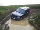
how deep184 views
|
|
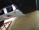
5mm Allen key showing the gap - can lift vertically to go flush111 views
|
|

LRO Show 2004 - Testing my 3 Month old Disco Metropolis - Those were the days!19 views
|
|

Wipers, Front and Rear, plus Washers description and operation.818 viewsThis 17 page pdf describes how the wipers, front and rear, plus the washers are intended to operate. Also described is how the rain sensor is designed to function along with a table of the wiper delay timing parameters.
|
|

Matzker photo showing their car using 25mm wheel spacers. Thus the outboard look of tires.406 views
|
|
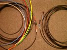
6mm PA12 grade nylon tubing with heat shrink applied 544 viewsShows some of the 6mm air line with heat shrink applied to one end of tubing. Shrink will be applied to the other end once field cut to length. These four tubes, each about 20 ft (6m) long, feed to the rear. Re the front air lines, (not shown), four additional lengths, each about 10 ft (3m) long, are required plus one more 3 metre length for compressor air. The 6mm tubing is a Nylon product specified as PA12. There is also a very similar Transport grade PA11 material, however it seems that PA12 is the more common Transport grade now in use. Also the applicable DIN standard seems to be both DIN 73378 and DIN 74324 for the nylon tubing. The working pressure of the 6mm tubing is about 27 Bar and bursting 82 Bar @ 20C. This is for the 1mm nominal wall thickness material, (4mm ID, 6mm OD).
|
|

Shift Lock Solenoid Problems14 viewsHow to repair and/or get home when the solenoid fails
|
|

LRO SHow33 viewsPeterborough LRO SHow
www.picman.co.uk
|
|

LRO Show34 viewsPeterborough LRO SHow
www.picman.co.uk
|
|

LRO Show37 viewsPeterborough LRO SHow
www.picman.co.uk
|
|

In the water splash191 views
|
|

Land Rover Aerial Fin images for both Glass and Metal Roof Disco3 / LR3864 viewsAs well as the two different fins, this pdf also shows the plastic blanking plate for glass roof vehicles where no fin is installed.
The glass roof fin is secured by two security screws from the top into a plastic frangible glue on gasket. The hope is that when struck, the fin will shear off and not crack the glass roof. Re the metal roof design, the fin is secured from underneath via two nuts.
The pdf also shows the various electrical bits related to the antennas. In the UK, the fin would house not only a cell phone antenna but the TV and satellite radio antenna electronics as well; in the States, the Sirius sat radio antenna and a G type cell phone antenna if the phone kit was installed would reside within the fin. The SAT NAV GPS antenna is located within the High Mount Brake Light plastic mounted to the upper rear hatch.
|
|

AFS Retrofit loom info77 viewsinformation about how to build a loom to retrofit AFS
|
|
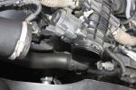
Air Box Removed1058 viewsView showing air box removed from front of EGR butterfly valve housing
|
|
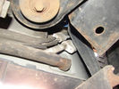
Air Conditioning Pipes (file 2)808 viewsShows location of front-to-rear air con pipes behind NS front wheel. You can just see the Vredestein tyre. The pipe connectors are tucked in behind the wheel arch inner cover. This has to be partially removed for access to bolts holding pipes together.
|
|
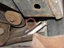
Air Conditioning Pipes188 viewsFront-to-rear aircon HP and LP pipes. The circled bit shows where the bolt securing the support bracket (removed)has sheared off
|
|
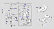
Thread upload413 viewsImage uploaded in thread 113599
|
|

Alternator female plug looking down into top373 viewsThis shows the plug connected to the alternator wiring harness looking down into the top of the plug.
The cavity marked 1 is the AS or BATT SENSE and the wire colour most likely has Brown/Green on it.
The cavity marked 2 is the RC or ALT CON and the wire colour most likely has Red/White on it.
The cavity marked 3 is the L1 or ALT MON and the wire colour likely has Green/White on it.
I say "most likely" as the wire colours are not always the same on all vehicles.
Also the terminal 1 conductor destination is more likely C0570-175 rather than per the jpg.
The #3 pin is located closest to the big B+ terminal.
|
|
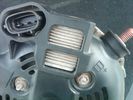
Alternator Plug and B+ terminal919 viewsPictured is the rear of the older Land Rover part # YLE500190 alternator showing the shiny cooling fin of the Regitar VRH2005-142 regulator under.
The first pin in the far left side of the connector is numbered #1 in the LR electrical wiring diagrams and is Battery Voltage Sensing (BVS); the middle pin, #2 receives a Pulse Width Modulated (PWM) signal from the Engine Control Module (ECM), and the right pin, #3 carries a PWM signal back to the ECM. Terminal Pin #2 on the LR wiring diagrams is called Alternator Control or ALT CON; Pin #3 per LR is called Alternator Monitoring or ALT MON.
Pin #1 is similar to what in older designs used to be called A or Batt, but is now called by Denso, S, AS, or Alternator Sensing for this design. Pin #1 also provides power to excite the alternator at startup until the PWM instructions over ride the battery voltage info. Land Rover calls the electronics under the pins a Smart Regulator, ironic, as it has to follow orders from the ECM rather than give the orders - new age thinking I guess. This is different from older design internal regulators that look at just the battery or the electrical buss voltage and then decides itself what to do.
It is almost like we are back to the external regulator designs of old, except that the ECM may decide that instead of telling the alternator to make more power, to load shed, and hence shut down the heated windscreen, seats, or whatever other electrical loads it decides are appropriate. My view is that the "smarts" are in the ECM and that the "regulator" should be regarded if not dumb, then as being a slave to the ECM.
|
|

Altox WBUS-4 Installation in Discovery 3127 viewsstep by step with pictures how to install the Altox WBUS-4 in the Discovery 3 in footwell
|
|

how to install Altox WBUS-4 in engine room on Discovery 395 viewsthis is to show how to install the Altox WBUS-4 in engine room of a Discovery 3, but i would recommend to install it inside car in footwell, see other PDF in this album
|
|

Setup Web application for Altox WBUS-461 viewshow to setup the Web application for Altox WBUS-4
|
|
Roof rails96 views
|
|

how did that slip in here322 views
|
|

Amp Drawing54 viewsThis is how many amps my vehicle was using when the ign in possision II. Lights where off, radio off,hvac off Crazy?
|
|
Andrew Shows us the fashion of the day - see the trousers151 views
|
|
Thread upload1 viewsImage uploaded in new thread
|
|

April showers280 views
|
|

Arm Removal Tool - shows offset29 views
|
|

Riparazione attuatore rotante volante - Steering rotary coupling repairing22 viewsCome riparare l'attuatore rotante del volante quando si accende la spia dell'airbag.
How to repair the steering rotary coupling when airbag warning light turns on.
|
|
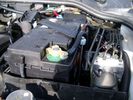
Aux Battery showing ground cable bolt "upside" down 1577 viewsIn order to obtain sufficient height clearance to get the plastic cover back on, I had to install the ground cable to the underside of the battery post connector.
Note the battery vent hose, (approx 5 ft required) is run down into where the windshield washer fluid container is located. There is not much electrical or metal in that area to be corroded by battery gas plus the open end of the vent hose tends to be protected from dirt and stays clean as well.
|
|
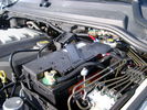
BCI Group 40R Deka 640RMF battery showing vent hose run forward to windshield washer reservoir area 1430 viewsRecessed post "Euro profile" battery to "match" OEM and stock Land Rover bracket; note that the Traxide SC80-LR module is mounted at an angle to allow for the main cable to sit under the cover so cover still closes.
The battery is a nominal 7", (180mm), high, but sits on a 1" battery spacer set under to raise the bottom front end of the battery such that the approx 11", (290 mm), length of the BCI 40R battery rises above the angled plastic nibs at the forward end bottom of the case front; hence sufficient space, (1/4", 5mm) remains at the brake reservoir end.
Also the 40R battery does not have hold down "flanges" on each end; on the sides yes, but not the ends so no additional length is required.
When I had to replace the 40R, this time I installed the shorter, (9.625"), taller, (7.5") Interstate BCI 47 / DIN H5 battery which eliminated the spacer on the bottom and better fit the stock LR tie down bolt lengths. Deka also has a BCI 47 / DIN H5 that would work fine as well.
|
|

Frame Jacking Points showing where holes are located.1088 viewsThe four points marked with the arrows show where the holes in the underside of the frame are located such than one could insert a trolley jack pin type lifting adapter, (or as designed), the official LR scissors jack.
|
|

A Pillar Black Plastic cover install pdf - new type.1039 viewsThis 3 page LR pdf explains how to install the newer A pillar plastic covers and avoid instant water leakage as a result of the new design.
|
|

showing off82 views
|
|
56 viewsType of car? How to get the Reg?
|
|
Shower at sea100 views
|
|
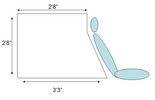
Dimensions67 viewsshown with 2nd row seat rake angle
|
|

Blanking Kit Fitting Procedure2449 viewsHow I fitted the kit to my D3.
|
|
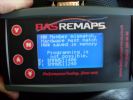
BAS remap interface after dealer software update287 viewsBAS remap interface after dealer software update,This is what you will be presented with after the dealer updates your cars engine software.
This is no problem IF you have returned the car to standard before the dealer visit.
When faced with this screen it will show you tht the dealer has changed the software and NOT let you put the BAS mapping back on your car because of the differences.
|
|
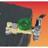
Battery Disconnect Wirthco 20308 Knob Top Post 890 viewsThis is a battery post style disconnect, usually for the negative terminal. There is a hole drilled in the round end off the battery so that flat terminal can be attached as well as the normal battery post terminal. I did not use this hookup arrangement, however I show it for information only.
|
|

Caterpillar Battery Size cross reference chart and battery profiles including post layout753 viewsThis pdf has a dimension, (metric and inches), cross reference chart plus another sheet that provides BCI and DIN cross reference numbers and shows post locations plus bottom ridge tie down locations, (or the lack of).
This data was for me, hard to find, and helps one in selecting a suitable physical size of Aux battery for the space available.
|
|

Uphill45 viewsPeterborough LRO SHow
www.picman.co.uk
|
|

Bin Cover removed showing forward release clips that clip into the two rectangular slots.10 viewsOne has to pull up on the Bin Cover to unlatch the two metal clips, hence why release of the C pillar cover makes the bin cover removal and reinstall easier.
|
|

Buzzer located under black plastic cover.12 viewsThe white electrical connector clicks into the buzzer housing that is shown protruding from under the black plastic cover. There is a little tab on the white plastic that has to be squeezed to release the connector. In other words, do not pull on the two conductors.
|
|

White plastic pin that has to be partly removed to assist in release of buzzer cover.11 viewsThe white coloured plastic pin is located near the C pillar and has to be partly pulled out to release the black plastic buzzer cover.
|
|
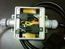
Box open showing Hella Relays and Putco Load Resistors749 viewsInterior of the box - note the two gold coloured 6 ohm 50 watt load resistors are a bit distant from the other items so as to provide some separation for dissipation of the heat generated.
Rather than a moulded plastic weather resistant box which I would have preferred, I used a bulky and much heavier metal weather tight style electrical box so the metal can act as a heat sink.
|
|

Black Deposits to interior of Brake Light Switch2862 viewsThere are two contacts, one on each side of the vertical plunger under the copper metal. The set of normally open contacts on the left side that carries the power for the brake light filaments, (15 amp fuse F15P), is apparently not heavy enough as the contacts deteriorate and generate the black residue.
The set of normally closed contacts on the other side appear to be sized OK. There is not as much current, (5 amp fuse F66P), flowing thru the contacts to the ABS module, however the contacts are likely adversely affected by the black residue produced by the other deteriorating set of contacts.
One presumes/hopes that the newer replacement switch now has contacts heavy enough to carry the brake light power. It would be ideal if the ABS set of contacts were sealed from the brake light contacts to prevent contamination of the normally closed set of contacts.
|
|

Brake Light Switch, Find, Remove, and Install Instructions 7854 viewsThis is a two page doc outlining where to find the brake light switch, how to remove it, and then install the new one.
Note, do not move the brake pedal when removing or installing the switch. Let the brake pedal hang where it wants to. The switch design is actually cunning, and as such is supposed to make the removal and install fool proof. Hence if you think too much about it, you can wreck the new switch.
If you want to inspect the interior of the switch, wait until you have removed the old switch. You can then just unsnap the blue from the white to get it apart. Inside, the switch is quite simple, (no circuit boards), but it will probably show black dust from failing contacts.
I think the reason the switch fails is that the Normally Open, (NO), contacts of the brake light contacts were made too light to carry the current load for make and break of the tail light filaments. I also think the black dust created then fouls the Normally Closed, (NC), second set of contacts for the ABS circuit. As such, the Normally Closed contacts become intermittent in operation and display as a fluctuating open and closed circuit condition to the ABS system when the ABS should be seeing a steady closed circuit. Hopefully the replacement switch contacts are more robust and may be as I recently replaced my switch again just as a matter of maintenance. While in a redesign, ideally the NC contacts should be sealed or at least separated from the NO contacts, when I inspected the removed switch, this time there was no black dust present.
Probably the removed switch will have a Land Rover oval logo moulded into it, the new one, FOMOCO.
|
|
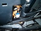
Brake Switch Visible thru Opening4975 viewsThe blue and white bit is the switch; the sort of gold appearing box,(it is really black), you will not see in your 3 as it is a Smooth Talker brand amplifier for my Blackberry phone antenna. This install is detailed in the SmoothTalker phone antenna section of my gallery.
One way to remove and install the switch is to lower the "horizontal" panel above the brake pedal as shown where the flashlight head is located. To actually remove the switch, you slide your hand thru the gap and rotate the switch clockwise 1/4 turn while watching thru the rectangular opening. Installation of the new switch is the reverse of above - 1/4 turn counterclockwise.
Before you remove the switch, note its orientation - horizontal with electrical wires to the left. That is the way it should look after replacement as well.
The second time I replaced the switch, I did it all thru the rectangular opening and did not remove the horizontal panel - that is experience helping out.
The knee kick you have to remove regardless. It is sort of hinged at the bottom so you just pull at the top and sort of rotate the knee panel and then pull upwards for two plastic "fingers" to clear the slots they reside in.
|
|
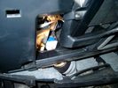
Smooth Talker Amplifier Box mounted below near steering column.179 viewsThe gold look box due to the lighting, (actually black), is the antenna amplifier located near the steering column. It can be put anyway but this seemed an OK location as I ran the antenna connector cable rearward from here to the back corner of the 3 and then up to the underside of the roof glass at the rear. The blue/white thing is the brake light switch that often must be replaced. See the Brake Light Switch file within this Gallery regarding the switch replacement.
|
|

Black Deposits on Brake Light Switch Plunger2758 viewsThis jpg I got off another forum and is typical of what one will see when one opens up the removed brake light switch. The black powder is residue from arcing of one of the pair of contacts within.
Hopefully the newer switches with the FOMOCO logo moulded into the plastic are improved from the Land Rover logo marked early units, however I doubt it.
The Ford part number is SW-6572 and/or 7E5Z-13480-A as used on the 2006 to 2009 Ford Fusion's and Mercury Milan's; the Land Rover part number is XKB500110. Cost of switch could be about twenty five dollars. A previous LR part number for the switch was XKB500030, so hopefully the newer LR part number, XKB500110, reflects some improvement in reliability.
It is possible that the new switches are better as I installed a replacement 72,000 km, (45,000 miles) later, at 195,000 km (121,000 miles). When I took the removed switch apart to inspect, it was clean inside. There was no black dust - the switch looked like new, hence they must be improved now.
|
|
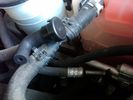
Breather line with factory cap cut off.2320 viewsIf you expand the jpg by clicking on it, in the bottom right corner if you look closely, one can see the black plastic factory vent tubing with the OEM cap cut off.
Note the tubing is cut at a 45 degree angle facing to the rear. Also shown in the top right is the cut off portion sitting on the coolant water hose and on the top left also sitting on the coolant hose, the new to be installed Gore manufactured replacement breather cap.
|
|
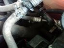
New Breather Cap installed.1713 viewsThis shows the new Gore brand angled breather cap installed. The cap points rearward to the firewall. Also shown is the cut off piece.
The new Gore breather cap is what one now sees on the LR4 and RR Sport.
|
|
Vertical Breather Hose before cutting off OEM cap.1779 viewsThis shows the plastic vertical breather tubing and OEM cap prior to being cut off. The tubing is located on the driver side at the front near the radiator. One cuts about 3/4" to 1" off from the top. The TSB says 20mm.
I tried blowing thru the cut off piece and was not very successful. The cap seemed plugged. I am beginning to think that there was a very good reason for Land Rovers's Technical Service Bulletin, (TSB).
|
|
Comparison with OEM bumper, shows approach clearance gained305 views
|
|
Burnt Bit97 viewsThis bit of wiring going to the connector was so close to bulkhead it got a bit burnt, Its for the clutch switch on a manual used for EPB, It will be replaced connector to pin with the wiring shown.
|
|
Cable loom cover406 viewsHow do you remove it???
|
|
D3 Side Step Repairs153 viewsHow I repaired my damaged side step after a days offroading at Tong in November 2008
|
|
Thread upload2 viewsImage uploaded in new thread
|
|
140 views
|
|
196 views
|
|
The Disco3 Squad, Saturday Morning216 viewsA stitch together of two photos showing all sixteen vehicles read for the off out and about in the Peak District on 1st July
|
|

74 viewsMS excel sheet for monthly mileage report will give average fuel consumption.(most cells have formulas to help fill in from previous line)
on first sheet add details you want on monthly sheets. during use the data needed to be added is ending reading on clock, places visited (if you want).
how much fuel when you purchased it also fuel in tank at start and end of month
|
|

506 views
|
|

Central Door Locking Operation Description1458 viewsThis 17 page pdf explains how the door locks are supposed to operate. Note that on page 9/17, the explanation of the operation of the hood ajar switch is wrong. It operates similar to the door and tailgate ajar switches; that is when a "door" is closed, the switch is closed to maintain a ground back to the CJB. Opening the hood, door, or tailgate removes the ground breaking the circuit and hence allows for an alarm condition.
|
|

How to spoil an Aston65 views
|
|
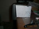
This show that the angel of the radio body is diffrent from the original, hence shall some plasic be removed - I used a dremmel and removed 7 mm of the horizontal bar inside 160 views
|
|
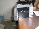
This shows the standard radio body angle161 views
|
|
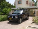
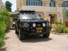
RHS view372 viewsSHows the Front Runner (SA) slimline windcheetah rack which is immensely strong. Takes my 110kg (oh gawd, I must get back on the diet and exercise regime) tramping over it when loading/unloading gear without a problem. Fittings are simply fixed or removed, and IMO very well designed and made. IPF 800 series driving and spots fitted to the front of the rack. IPF cam/reversing fitted each side and to rear of rack for negotiating rocky wadis at night. The G4 stickers were bought off E-bay as a set.
|
|
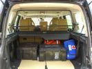
Load space369 viewsShows the SA Front Runner Wolfpack stacking plastic storage boxes that I keep laod straps etc in and the 2nd is tool kit, spare belts, jerry can funnel and tools, plus airline and tyre inflator/deflaotr for ARB on-board compressor, HD jump leads. ARB Winch pack (Orange)with strops, snatch blocks, shackles, gloves, and 2 ARB recovery dampers. Really great 4x4 1st Aid kit from Outdoors warehouse in SA. LRs own loadspace guard - not the best design if you want to store a long load. Mods to be carried out!
|
|
Lookalike 2009? 309 viewsShows RHS wheelarches, sills and door mirrors sparyed to match body colour.
|
|
Clip Spring Metal FYC 500040 that holds LR together1747 viewsThe jpg is of the spring metal clip, Land Rover part number FYC 500040 that holds most of our 3 together - well at least most the interior trim parts.
If you are going to remove interior panels, you may as well stock up on a few for replacement as upon panel removal, the clips tend to spring away into deep never to be found voids within your 3.
|
|

COMM FAILURE in the Faultmate FCR79 viewsThis is ONLY shown if either you have a communication error or in most cases you dont have fitted on your car the module you are trying to communicate with.
|
|
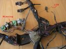
example problems113 viewsInspection showed another Cut Airbag connector, a Missing connector and a few rogue wires at the bottom, the silver one marked Lin, is for the LIN BUS and is supposed to be like that though
|
|

Cooling system hoses - 4.4L petrol V81110 viewsThese are the cooling system hoses on the 4.4L petrol V8. The little odd shaped bleeder hose, (LR006158), shown in the top right hand corner can give problems. There is a plastic tee with a threaded air bleeder outlet located in the middle of the hose. The plastic tee can or will fail due to I guess heat distress.
A BIC pen can serve as a field fix, however for your parts kit, a nominal 3/8" ID hose size brass hose barb inline connector plus a couple of hose clamps is suggested. Better yet is a threaded hose barb brass coupling or a tee and bleeder valve to allow bleeding of the line. Land Rover now makes the plastic bleeder valve that breaks available as a separate part, # LR027661, where 0 is a zero. As such, one can now purchase that part only for addition to your field fix parts kit.
|
|
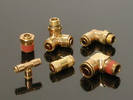
Detroit Fluid DOT air line fittings718 viewsThe picture shows the internal ferrule that is characteristic of the DOT / TUV accepted fittings for highway vehicles. Most often these fittings are metal however the Land Rover John Guest 6mm straight connector is all plastic and has the internal ferrule.
|
|
Lro show 13th sept 0943 views
|
|
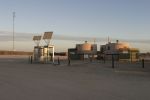
Phones, Public Toilets & Showers at Innamincka82 views
|
|
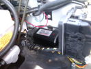
CounterAct Power Supply mounted 247 viewsPicture is blurred, however power supply is 3M two sided tape to the flat black plastic of the second battery compartment just under the antilock brake pipes to the fender side of the brake fluid reservoir. The white wire to the left rear coupler pad runs thru the firewall hole near the steering column. The blue wire to the right front coupler runs across and above the engine following the other wiring looms that cross the vehicle.
|
|
CounterAct Power supply mounted under brake lines.194 viewsThis top view shows where I located the power supply. It is attached with 3M sticky to the black plastic surface that is located under the brake lines.
When the system is operating properly, the red LED pulses about twice per second.
Some users claim they can hear a very slight hum or whine coming from the unit. My unit seems silent.
|
|
Engine Cover Removed901 viewsView of the engine before blanking off the EGRs. The inset sort of shows one of the EGR valve/pipe flange securing bolts. The EGR valves are not easy to get at!
|
|
Near side showing interior227 views
|
|
Drivers seat wiring Cut151 viewsSpare connector from my second hand seats shows where wiring to seat gets cut presumably by emergency services.
|
|

C pillar cover removed to facilitate removal of bin cover.9 viewsNote the "ribbon" behind the top left corner of the C pillar cover. This is something to do with the curtain air bags, hence do not mess with it. I dislodged the cover to make it easier to pull up and extract the black plastic bin moulding. It is not necessary to totally remove it and would be what I call a big deal - seat belt, air vent and ducting as well as that curtain concern.
|
|

25 viewsCERS Founder and China's 'greatest living explorer' Dr Wong How Man joined the Journey of Discovery in Dunhuang, China - a symbolic intersection of the Silk Road where the East meets West.
Interactive Land Rover MENA
|
|
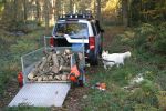
D3 at work, also showing my helper bringing me logs to cut420 views
|
|
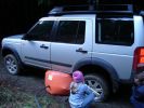
Lakeland DPs daughter shows changing wheel is childs-play.314 views
|
|

Info on how to change the green & gold ovals to silver & black587 views
|
|

Hog Rings and Hog Ring Pliers47 viewsHog Rings and Hog Ring Pliers showing an open and closed hog ring with 20p for scale
|
|

42 viewshow to replace the speaker on a D3 instrument cluster
|
|
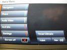
Main Navigation Menu showing 4x4 info and timed Climate173 views
|
|
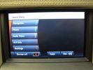
Main Navigation Menu showing 4x4 info 143 views
|
|

D4 Gvif Unit Fitting28 viewsHow to fit Gvif unit to a D4 sat nav screen
|
|
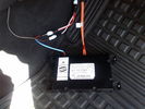
D4 Bluetooth AH42 10F845 AA module connected to 12VDC and MOST1210 viewsThis jpg shows the MOST bus connected to the AH42 10F845 AA module used in the D4 as well as +12VDC power from F58P connected. The power is split with a Y harness as the IHU (radio) for some reason required +12VDC power to the C2115-10 "mute" pin to keep the radio/CD audio from muting all the time.
With power on the pin, the radio audio does mute as it should when the cell phone rings and the hands free connects. The brown conductor feeds to C2115-10 and the blue to the module.
The module tucks up and hides behind the grey plastic section covering the forward portion of the passenger side tranny hump for left hand drive vehicles; for RHD, it would be located on the left side.
The pairing code is 2121 with this setup and not 1234 or 0000.
|
|
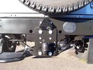
Defender 19 viewsDefender showing trailair camera fitment
|
|
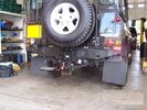
Defender22 viewsDefender with adjustable tow bar showing trailair camera fitment
|
|

Defender in the Fog, another day on the job.459 viewsThis is another normal work day for a Defender - actually the jpg is from a Land Rover advertising shot, but it may just not be a set up one. I think it is an actual working Defender. Note the visible front tow hook and how the hi lift is just rope tied on; also the normal stock headlights and I guess dual spare tyres - just another day on the job.
|
|

Deka Battery Dimension Data615 viewsThe battery size that I installed for my auxiliary was a BCI 40R battery as it was for me the easiest to fit and was also a cranking battery. The case profile was such that no tie down fins were located on either bottom end, (sides yes), and length wise, it was only about 11" (290 mm) long. As such, I did not have to grind the nibs at the front bottom of the plastic surround.
I did however raise the bottom of the battery above the angled nibs as I set the battery on a 1" (25mm) high plastic spacer. The total height, (battery plus spacer), was about 8" (200mm) so the battery top still fit under the Land Rover factory cover.
For the Aux battery, when I replaced the 40R, I installed an Interstate BCI 47 which is similar in size to a DIN H5. I was therefore able to eliminate the vertical spacer as the Group 47/H5 is the same height as the DIN H7/H8 stock LR spec starting battery. As such, the standard battery tie down bolts can be used without modification. The Group 47 battery is 9 11/16" long x 6 7/8" wide x 7 1/2" (190mm) high.
|
|
Dented side rails265 viewsShows how thin the metal is.
|
|

Older Cell Phone handset holder operation and components849 viewsThis 8 page pdf explains the operation of the older Cell phone handset holder and shows the various components as related to the radio and phone buttons etc.
|
|

Cooling System - Description and Operation 4.0L and 4.4L petrol engines 5 pages1028 viewsThis is a 5 page pdf that provides some insight into how the coolant flows thru all the hoses. Of interest is the paragraph,(page 3/5), that attempts to explain how and why the thermostat is designed to open at different engine operating temperatures - in brief, the reason for the spaghetti tangle of small hoses on the top of the engine.
There is also reference to an engine oil cooler that I gather cools something I think related to a supercharger, if fitted.
|
|

415-03 Audio System - Low and High Line Radios934 viewsThis 8 page pdf shows both the low and high line radios and their various components.
|
|

58 views
|
|

Thread upload17 viewsImage uploaded in thread 170233
|
|

Thread upload21 viewsImage uploaded in thread 170233
|
|

19 views
|
|

Detent_Circlip_How_to225 views
|
|

Video showing TR working to counter wheelspin573 viewsTaken at off road day in Henley In Adren Warwickshire, a good fun day out.
|
|
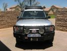
260 viewsARB bull bar, Hella 2000 series spots, Warn winch & Hella low profile rr mounted spots, expedition rr & Howling moon awning.
|
|
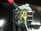
190 viewssignal wire pin 3 on rear of D4 rear light plug fit 6 ohm 50 watt resistor across here and common ground Pin 5 yellow terminal shown in next pic
|
|

Disco 3 - Suspension Leveling & drop check worksheet32 viewsUsed to work out how much your disco drops on its suspension and if its outside of the standard tolerances.
If you have any suggestions on how it can be improved please let me know.
|
|
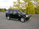
Disco 4 in west Midlands321 viewsDisco 4 (MY10) in Bournville, just out of show room.
|
|

Disco 4263 viewsDisco 4 (MY10) in Bournville. Just out of the show room!
|
|
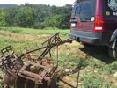
LR3 to plow your garden298 viewsI found this jpg where a current LR owner is using his LR3 for a similar purpose as the original Series units were designed to do - that is serve as a tractor for plowing a field or I suppose a garden.
In this case, I note the hitch is one of those that attach to the factory tow loop, (Rhino Hitch), rather than the factory product that inserts from the bottom and hangs down - (like a plow), but all the time. One of the other jpg's in this album shows the two factory variations plus a third jpg shows a closeup of the Rhino Hitch.
|
|
Dom, this is how its done!403 views
|
|
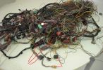
Donar Loom100 viewsThis ball of wires is from a LHD which has been opened and had all audio wires removed, however it is a gold mine for the bits i need. I have pointed out the connectors i know i need for starters near the bottom.
|
|

Driving 101 - a humourous PowerPoint Presentation file148 viewsItalian and humourous. Turn the sound on and have a quiet chuckle at the show. Only let the children watch if they are able to accept animated violence (some life forms were injured or killed in the making of this animation!!).
|
|
My LR3 taking a shower230 views
|
|
13th Sept LRO Show off road course38 views
|
|
13th Sept LRO Show 47 views
|
|
Trailer how it used to be259 views
|
|

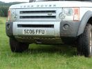
Discovery Owners' Club Stand, Gaydon 2005817 viewsScorpio's D3 (on the left) with a LR owned Disco on the DOC's stand at the Gaydon Show 2005
|
|
ARB Bull bar - closeup of drivers side showing trim finish.244 views
|
|
ARB Bull Bar - closeup showing trim finish of Wheel trim.224 views
|
|

63 viewsYou can see how the spot to mount the control box has the long flat section to the left - so I mounted the box upside down to allow the 2-sided tape to stick to this bit.
|
|

Papa King shows us why you never travel alone198 viewsAll of a sudden the sand became spongy, and Kingsley\'s vehicle just sunk in up to the chassis. Took the guys quite a while to dig and winch it out.
|
|
For Showing52 views
|
|
RLD shows who's boss435 views
|
|

Rear ladder showing black & silver LR logo216 views
|
|
Babu - great guy from Mozambique who joined Kingsley\'s core team.158 views"How the heck am I gonna fit all that in there?!"
Packing all the kit in Ondangwa. Amazing what you can get into a Defender!
|
|

Paulo showing a Himba warrior his own photograph148 views
|
|

IBS contoller showing battery condition (engine off)218 views
|
|
Showing neat winch set up. Front cover removed251 views
|
|
85 viewsFuel filler, showing rear diff breather pipe
|
|
103 viewsRear shot, showing diff and fuel tank breather pipes running up to filler neck at top LHS
|
|
Dead engine135 viewsExhaust ports showing where leaked coolant has gone into the manifold and filled the turbo
|
|
Recovery hook113 viewsMakes it clear how the front recovery hook is mounted into the chassis
|
|
Mantec plate on show at Drumclog.179 views
|
|
D3 Commercialisation622 viewsThis is the pic that was sent to me by the dealer to show what would be done to turn my SE into a van. (The car shown isnt mine)
|
|
Showing Extent of \'extended mode\'392 views
|
|
Damaged area66 viewsPic shows plastic breather fitting with the corner ground away. When tank reached full fuel is pushed out under forecourt pump pressure. The second occurrence shows similar damage.
|
|

Another view50 viewsA view of the general area showing the damaged part, lower centre. The second occurrence shows similar damage.
|
|

2nd Row footwell, showing water dispensing hose144 views
|
|
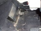
Internal water tank right side view162 viewsShows right front side of tank, with RH seat lifted. Note seat bolt is used to also hold the tank secure. This is a 5-seat D3, which has a cover over what is normally the 3rd row footrest. This is where the water tank is located.
|
|
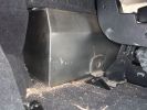
Right side floor-level view of water tank.151 viewsShows tie-down bolt (one of 2 securing the tank). Also note small void on side, which permits tank area to dry out if accidentally overfilled.
|
|
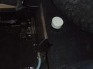
Internal 40 Litre water tank - top view of left side of tank106 viewsShows my spare tyre, but also bright white protective cap of top fill point and vent. Blue hose is water dispensing point. Note seat bracket bolt secures tank to D3. Similar bolt point on other side. Only these two bolts secure the tank and it is very secure.
|
|
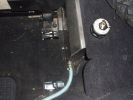
Top view Left side of water tank128 viewsThis view shows the protective cap off, displaying tank vent point.
|
|
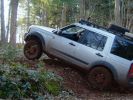
Boughrood 7/4/7318 viewsHow many wheels has Chris got on the ground?
|
|
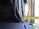
Left side (looking forward) of radiator after grill and bumpers removed.103 viewsTape measure is shown for illustration of dimensions only.
|
|
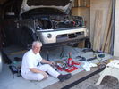
Installed winch, with bumper partially re-installed203 viewsPutting the D4 back together. Shows the tools and owner lying about.
|
|
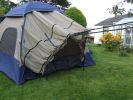
Tent showing vehicle 'sock'167 views
|
|

Photo showing inside sock.166 viewsThere is a double layer inside. Just like a conventional tent, the waterproof layer, then a flysheet. Both can be zipped/unzipped when vehicle is not in place.
|
|
View of both hose connections to power steering system153 viewsBoth connections are shown. My friendly Qantas hydraulic hose expert cut off the elbow and modified it so I can re-install it to the PS rack before warranty work (and certainly before the vehicle is lifted off the body!!).
|
|
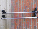
Showing manufacturers designed profile in bars.21 views
|
|
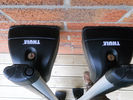
Showing Thule locks21 views
|
|
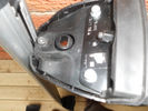
Showing T-trax feet adaptor.24 views
|
|
Security cover off showing lock.22 views
|
|
Base showing tiny crack31 views
|
|
The morning after193 viewsJust how good does she look today!
|
|
maxxraxx fitting - showing electrics now accessible!400 views
|
|
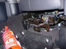
Mounting a non-LR fire extinguisher535 viewsShowing the plastic cover removed. I will make up a metal plate or bar so that the extinguisher frame can be mounted directly to this framework under the seat.
|
|
Roof Bars closer84 viewsRoof bars for sale, showing small cut/nick
|
|
Lr show 201713 views
|
|

LR show 201714 views
|
|
LR show 201714 views
|
|
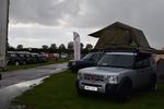
LR show 20179 views
|
|
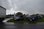
LR show 201712 views
|
|
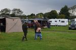
LR show 201710 views
|
|
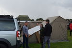
LR show 201710 views
|
|
LR show 20179 views
|
|
LR show 201712 views
|
|

LR show 201715 views
|
|

LR show 201710 views
|
|
lr show 201710 views
|
|
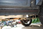
194 viewsRight front showing rough fit of the slider
|
|
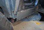
183 viewsRough fit showing the rear end with the support channel and slider plates.
|
|
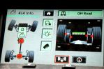
4x4 info screen showing both diffs hard at work146 views
|
|
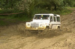
LRO Show Billing 200222 viewsTaking the fairly standard 110 round the course, we did ok.
|
|
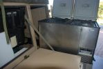
121 viewsthis shows the fridge on the 2 x 180kg sliders. i had to slightly modify the door opening to fir the fridge hinges thru. I just gently bent it, and fitted additional seals, hence it can easily be returned to standard. having the fridge in the kitchen is a major bonus, plus the back door of the trailer is now used for easy access to the cavernous interior, whereas prior to this youhad only access thru the front doors, which are only 500mm wide
|
|
G4 sankey and howling moon tent 2164 viewsG4 on 2008 GToN www.gton.co.uk
|
|
G4 sankey and howling moon tent139 viewsG4 taken on 2008 GToN www.gton.co.uk
|
|

Showroom 19 views
|
|

Showroom 210 views
|
|
Multimedia in my D387 viewsSome pictures on how 12h of work made a difference to my D3
|
|
The swinging lump of iron that sit under the back,871 viewsLook how close it is to the wiring!
|
|

D pillar speaker cover removed to facilitate removal of the bin cover.11 viewsThe pipe thing exposed when the D pillar cover is removed is something to do with the side curtain air bags and hence is not to be disturbed - at least my me. Removal of the cover make lifting of the bin cover easier.
|
|

Earth Strap Fix8 viewsHow to fix the corroded engine to chassis earth strap
|
|

How to re-close the EGR clip with common tools160 views
|
|

Fuel Purge Valve and other hoses.846 viewsThis 6 page pdf shows the Fuel Purge Valve and associated hoses and describes how it is supposed to work. There are lots of good drawings of the fuel system. It is more complicated than one might think.
|
|
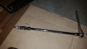
Thread upload18 viewsThis is how you reach that TOP BOLT holding your air compressor bracket on. 10" extension, swivel, and 10mm socket taped so it won't fall off while your feeding it through the air compressor maze.
|
|
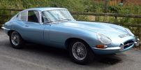
Jaguar E Type S1 4.2 Coupe6 viewsFactory restoration to near concourse condition almost complete. Disco 3 purchased as towing vehicle for shows.
|
|
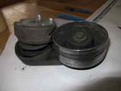
24 viewsshowing the tensioner deformed
|
|
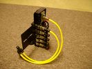
FASKIT on end view 864 viewsEnd and rear view of the FASKIT. Yellow lines are as shipped for hooking to the air supply; one line to valve/filler and other is to gauge. I will modify the arrangement to delete one of the yellow lines such that gauge line plugs into where the second yellow line is right now,(will be only one yellow tube), and then the air source line will plug into the port controlled by the valve, (hidden in this view but visible in other view). When white valve is in the ON position, gauge will read air source pressure, and be available to supply air to any of the selected four air springs. When valve is closed, the gauge will show individual air pressure in each of the air springs when a jumper is run between the gauge Schrader valve and the appropriate air spring Schrader valve.
|
|
FASKIT rear showing gauge.922 views
|
|

Pass seat wiring108 viewsClose up showing the re worked Pass seat wiring on the D3 loom next to the sport one.
|
|

The full story how I fitted RSS seats in D3520 views
|
|
Underside showing various thickness of packing137 views
|
|

Lots of tips for a visit to Florida13 viewsHow to get the most out of your trip to Florida.
|
|

Fluid, Filter/Pan Combo removal and install5980 viewsThese are the LR instructions re removal and install of the plastic pan/filter combo for the ZF 6HP26X transmission on the 4.4L petrol V8 LR3.
The instructions tend to ignore the reason you have to lift the right hand side of the engine about 40 mm. This is because of a frame cross member that interferes with dropping down of the plastic pan. The real problem is a vertical "oil filter spout" that rises out of the filter/pan combo up into the transmission. The spout is the suction pipe for filtered transmission oil back up into the tranny.
On the metal pan versions, the filter is separate from the pan, hence the filter remains with the tranny when the metal pan is dropped. The filter is then removed or installed independent of the metal pan, hence with the metal pan, there is no need to lift the engine.
If one is removing the plastic pan so as to install the metal pan, then some do not lift the engine but just drop the plastic pan enough to gain access to saw off the vertical plastic spout - it is a one time procedure.
Be aware however that the metal pan uses a flat gasket and the plastic pan uses a O ring like perimeter gasket that sits in a half round groove in the tranny casing. Also the metal pan uses 21 shorter torx M6x22.5 metric cap screws for the perimeter bolts. The plastic pan uses longer M6x28.5 torx metric cap screws.
|
|

Thread upload16 viewsImage uploaded in thread 110148
|
|
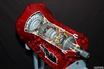
Ford 6R60 six speed cutaway showing torque converter.2198 viewsThis is a cutaway of the Ford 6R60 six speed which is a Ford license built version similar to our ZF 6HP26 six speed speced on early 3's.
The newer 3's and 4's have the ZF 6HP28. The Ford version is called the 6R80 and variations of it are used on the Raptor. As such, the Raptor metal pan can be installed on the 3's tranny but the deeper Ford Raptor pan does not have a drain plug.
|
|
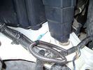
Front coupler pad to right front under air filter housing 160 viewsCoupler Pad is attached to the flat metal surface just behind the rectangular drain off of the air filter housing. The last 3 inches (75mm) of the 1/4" (5mm) black flex wiring loom was then threaded over the last bit of wiring. One of the other jpg's is less washed out and shows the coupler pad a bit better.
|
|

First showing of Front Lamp Guards on the Discovery 4164 views
|
|
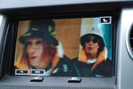
Front screen mod241 viewsMy rear DVD now shows up on my front screen thanks to Woodmans video guide!
|
|

Official instructions on how to remove the bumper909 viewsWhen removing the front bumper - you start with the front grill, then the headlamps, then the wheelarch trims, then the bumper...
|
|

Official instructions on how to remove the wheel arch trims624 viewsWhen removing the front bumper - you start with the front grill, then the headlamps, then the wheelarch trims...
|
|

Land Rover TSB LTB00245 install instructions1940 viewsThis is the Land Rover Technical Service Bulletin showing how to install the new breather cap. The instructions are a bit vague re cutting the existing air vent tubing on a 45 degree angle with the cut facing to the rear.
|
|

Front_clearance_offroad_mode754 views275/65/18 Cooper Discoverer STT mud tires - minimum clearance between front wheel and crappy plastic wheel arch. Although it lokos tight, there is actually more room between the tire and arch than the pictures shows.
|
|

Breather Hose exploded view.1232 viewsThis pdf shows the exploded view of the breather hose from the front differential to the engine compartment. The breather hose part number is TAP500081 and is identified as 4A058 in the drawing.
|
|
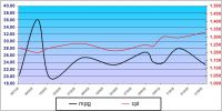
MS Excel chart of fuel usage in TDV6 first 3 months of ownership201 viewsReason for distortion at beginning is not known - average so far is 11.55l/100k (25.09mpg) for the 6 199k travelled. The fuel usage 'bumps' correspond with the city driving although they did mirror the cost for a while! A copy of the spreadsheet (105kb) that shows MPG and l/100k (but not miles) is available for the asking - just PM me.
|
|
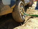
Rear wheel dig116 viewsYou can see here how much the right rear tyre has descended into the furrow we dug.
|
|
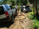
Winch/snatch block113 viewsThis picture shows the winch in position.
|
|
45 viewsHow not to have someone deliver your Golf
|
|

Gore Tex Oleophobic Membrane Vents82 viewsThese is a link to a Gore website that explains how the Gore Tex material within the breather cap allow pressure to escape (but retains the oil) and allows moisture free air to come back in but excludes free water.
|
|
Left Headlight15 viewsLeft Xenon headlight showing adjusters
|
|
SDD hitachi file selection56 viewsSDD screen shot showing files selected with an Hitachi compressor
|
|
Rhino Tow Loop Hitch270 viewsThis is a receiver end view of the Rhino Hitch that ties to the factory tow loop. In addition to improved strength, it does not reduce ground clearance as does the factory style when installed.
Land Rover in early advertising videos when the 3 first came out showed the D3 hanging from a crane via the frame. The intent was to show how strong the frame is and by inference, the rear tow loop, specifically noted as being good for 6 tonne. The video ends before anything dropped or was lowered back to the ground, so one of course does not know for certain. The Rhino Hitch design however picks up on the apparent evidence of strength and certainly the additional clearance.
|
|

376 views
|
|

D4 Sat Nav Manual - How It Works section121 views
|
|

How to swap front panel of HEVAC Unit65 views
|
|

Thread upload15 viewsImage uploaded in thread 135371
|
|

Hownams Hill repeater D4 Launch95 views
|
|

399 views
|
|
![Filename=how_i_made_the_exorcist_7_a_l[1].jpg
Filesize=55KB
Dimensions=648x365
Date added=10.Feb 2014 how_i_made_the_exorcist_7_a_l[1].jpg](albums/userpics/13441/thumb_how_i_made_the_exorcist_7_a_l%5B1%5D.jpg)
Thread upload18 viewsImage uploaded in thread 107188
|
|
Thread upload18 viewsImage uploaded in new thread
|
|

How To - AMK Suspension Compressor Replacement by Disco_Mikey20 viewsA copy of Disco_Mikey's guide on how to replace AMK Compressor, complete with photos.
|
|

Denso Bearing Change105 views
|
|

How_To_Change_the_Oil_Pump_Casing_to_the_New_Beefed_Up_Front_Cam_Belt_Tensioner.pdf113 views
|
|

Armrest Fitting116 views
|
|

989 views
|
|

Thread upload16 viewsImage uploaded in thread 139602
|
|

Back of unit shows choice of port for best fit94 views
|
|

Well, would you swin in this. The pic doesn't show it, but this Loch looks a tad on the iffy side, and its drinking water ????157 views
|
|
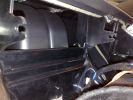
OE 2 cut dash showing top72 views
|
|
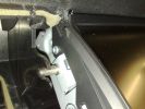
OE cut dash showing where to cut72 views
|
|

OE cut dash with display fitted - showing where to cut76 views
|
|
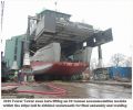
Messing with boats112 viewsShows our 300t capacity Lift System holding up an 80 tonnes module as the hull is winched underneath for final lowering and welding together.
|
|
79 viewsLRO Show 2008
|
|

Post Suspension Calibration57 viewsA spreadsheet I made showing results of suspension calibration using Gap Diagnostics IIDTool
|
|

Pre Suspension Calibration59 viewsA spreadsheet I made showing results of suspension calibration using Gap Diagnostics IIDTool.
This is the pre-existing values
|
|

Thread upload22 viewsImage uploaded in thread 160177
|
|
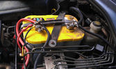
The auxiliary battery21 viewsThe auxiliary battery in the bay.
As the wiring diagram I made shows, there's a wire leading to the fuse box in the rear. (is going through the key-switch)
The second one is going to the fog lights. The smaller cables which should be connected to the head-lights, are connected to the battery.
The third one is going to the compressor (via a switch) (sits before the key-switch)
A fourth one is going to the CB and battery check display (sits before the key-switch)
|
|

President Johnson II in its current position19 viewsThis CB was installed some years ago and still is at the same location.
However, I'm planning to move it to the head unit area.
As such, I'm looking around to replace my low end head unit with a single DIN radio and the CB on top of it.
|
|
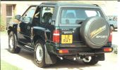
1994 Vauxhall Frontera, how they ever got away with calling it a \'Sport\'!119 views
|
|
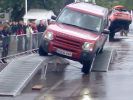
Royal Show 2007 Terrapod100 views
|
|
How not to cross a ford..192 views
|
|
Royal Show 2007 Terrapod103 views
|
|

Rotal Show 2007106 views
|
|
640 viewsCup holder panel showing the 8 locating lugs and clips
|
|

Royal Show 2007 Terrapod106 views
|
|
Royal Show 2007 Terrapod101 views
|
|
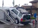
Royal Show 2007 Terrapod110 views
|
|
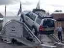
Royal Show 2007 Terrapod98 views
|
|
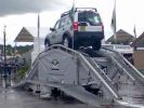
Royal Show 2007 Terrapod95 views
|
|
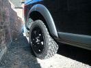
Rear Black wheel with MTR showing aggresive tread pattern544 views
|
|

Puzzle - how do I get to that cat on the other side?52 views
|
|

CV boot puncture 84 viewsThis is how the cat was returned from the garage
|
|

89 viewsThis is also how the car was returned after being repaired
|
|

Loose bolt 89 viewsThis is how my car was returned from the garage
|
|

LP scoped 222 viewsBy connecting a Low Amps probe to the fuel pump's voltage supply wire, you can view the pump's current waveform on a digital storage oscilloscope (DSO). The scope pattern will reveal internal wear in the brushes and commutator that may not show up in a traditional pressure or volume test.
Observing the waveform will show if the pump's amp draw is normal for the application or is high or low, and if the pump is operating at normal speed or is running slow. Problems such as a bad spot on a commutator or a short or open in the armature also will be obvious in the waveform.
A "good" electric fuel pump waveform will generally seesaw back and forth with relative consistency and minimal variation between the highs and lows. A "bad" waveform will show large or irregular drops in the pattern, with large differences between the highs and lows.
|
|

Dash View 0194 viewsShows remote radio head (FT-8900), fist microphone and sat nav. Mic is fixed using Velcro...
|
|

Windy79 viewsPepper showing that it was windy on the Cairn
|
|

1522 viewsPicture showing two sub bass units and the computer mounted on a board in the newley aquired space.
|
|

777 viewsShows the newly aquired space with the lid down, this will be covered with the right carpet as soon as i get my hands on some
|
|
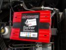
Aux Battery1054 viewsShows the aux 65Ah battery in place, top left of the picture is the 100amp circuit breaker feeding items sutch as , inverter, sub bass amplifiers, computer.
|
|
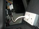
220v Socket894 viewsPicture showing the back of the Inverters 220v socket
|
|
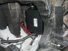
1634 viewspicture showing the location of the "Lodar" radio winch remote control box.
|
|
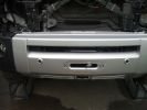
1858 viewspicture showing the finnished bumper, i think it looks quite cool
|
|
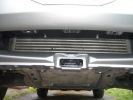
1844 viewsPicture showing no obstruction to the Intercooler, The winch is above it.
|
|
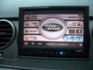
View showing media player screen2447 views
|
|
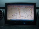
View showing nav screen.1651 views
|
|
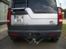
Showing rear view of the two pipes.795 views
|
|
Shows the tail pipe of the exahust756 views
|
|
Showing 2200lb winch198 views
|
|

Showing compressor, tank, pressure switch569 views
|
|
Kent Show Ground 19/04/0993 views
|
|
Showing the HID ballast units575 views
|
|
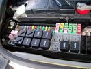
Picture of the engine compartment fuse panel5780 viewsEngine compartment fuse panel located near the battery. This is where F3E, (5 amp), F26E, (20 amp), Fuseable link 10E, (60 amp) and Relay 7E, the now upgraded 70 amp air compressor motor relay, part number YWB500220, (E is for Engine compartment fuse box), are all located. Fuse F35P, (5 amp), is inside the Passenger compartment behind the lower glove box door.
To keep the suspension from going down to the stops when driving, (or parked), it appears that it is only really necessary to remove F26E to depower the exhaust valve and generally keep all the valve block solenoid valves in a closed position trapping whatever air is within the air springs. F3E gets its power thru F26E, so when F26E is removed, the F3E circuit is automatically de-powered. F35P is more interesting in that battery power goes thru the ignition switch and F35P and then into the air suspension control unit. Apparently however, if F26E is removed, removing the F35P is not needed even when the engine is running.
With all fuses still in, if you have a problem, in practice, ideally, the compressor still works and will raise the 3 to an appropriate height. If so, one can then shut the engine off and allow the computers to go to sleep and then you remove the fuse(s). In actual practice, it seems that one need only pull the F26E fuse and can do so with the engine running. All the same, one might consider that the 3 is first a mobile computer, and secondly a 4x4. Computers prefer to go to sleep before the plug is pulled on them, however given that F26E circuit is always alive, then the computer never sleeps. With the fuse(s) pulled, and if you are still up, you can now be a 4x4 instead of a low rider. The whole purpose of the fuse pulling exercise is to depower the one and only system exhaust valve that is physically located within the compressor unit, (to keep it from opening), and secondarily to keep closed the four air spring solenoids within the block valves. This also shuts the air compressor down and stops the air compressor from making air even if the compressor is still good. That is why you initially need the fuse(s) in to allow the compressor to make air if it can.
|
|
CALENDAR 2010364 viewsCALANDER 2010. TAKEN AT BERKSHIRE 4X4 SHOW DOING TIME TRIALS 3RD PLACE
|
|

top left hand side fitted66 viewsto show how its angled to fit in with the mouldings
|
|

child cage70 viewsdont call the NSPPC just yet just to show how a 2yr look in the cage
|
|
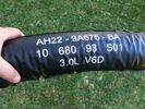
Bottom of airbox, showing one-way valve and locating lug178 views
|
|
Inside factory air duct - showing felt-like material (used to absorb fumes)153 views
|
|
Factory air duct - showing vinyl covering155 views
|
|
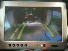
D4 Reverse camera view - shown on 10" screen39 views
|
|
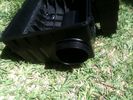
Airbox showing inner inlet tube poking through191 views
|
|
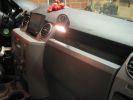
433 viewsA glimpse of the final installation, with a working map-reading light. In case the GPS doesn't work ;p
This is an old picture as the touchscreen is removed already.
However, I kept the reading light.
|
|

Loadspace73 viewsLoadspace showing the UK Commercial spec loaded arrangement.
|
|

iPhone Gas Cubby19 viewsScreenshot showing the fuel economy of the LR4
|
|

Christmas Express50 viewsThat´s how christmas trees should be brought home!
|
|
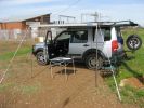
Marshall point Caranval 400267 viewsHowling moon awning.
|
|

Sunday, December 4th, 2011 at 7a.m. in Amboseli National Park, Kenya (East Africa)227 viewsThe top of Mt. Kilimanjaro showed it self for 15 minutes in the morning and my buddy snapped this picture of me and my Disco 3 from a Defender while on a morning game drive
|
|

led boot space light upgrade96 viewsClose up showing how easy the led ultra bright modules fits into original housing
|
|

Discovery 4 DRL 117 viewsThe photo shows the Land Rover Discovery 4 fitted with the Land Rover Daytime Running Lights. These were fitted by Land Rover when I got the car. The are on when the lights are not. As soon as the main lights come on the DRL's switch off.
|
|
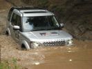
D4 showing us how it is done197 views
|
|
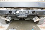
Towbar showing rear brackets554 views
|
|
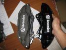
Brembos - FFRR vs RRS 01131 viewsHaving acquired the wrong calipers and discs initially, I purchased the correct RRS kit from TLO. Useful picture - the light grey calipers show that the FFRR has a smaller offset mounting point and smaller diameter threaded holes. The glossy calipers are for RRS and fit D3 perfectly with correct offset and M15 mounting holes.
|
|

In show room just doing the paperwork before collecting keys92 views
|
|
South Australian Landrover Show - Melrose 201318 views
|
|

D3 Rear Tailgate switch headliner connector8 viewsThe black connector in the headliner of a D3, showing the brown wire being pushed back and not making contact, and stopping the rear button from working
|
|
dont know how to call it removal (omocinetico)71 views
|
|
dont know how to call it (omocinetico calettato)77 views
|
|
106 views
|
|
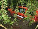
LRE Eastnor G4 D3582 viewsCALENDAR ENTRY
Photo taken during the LRW Show at Eastnor Castle, 6th June 2009.
The LR Experience G4 D3 was moving in to position to help out a stricken RR Sport that had gone off track and ended with its\' nose in the trees. A very impressive front (another LRE D3) and rear winching method to extract the RR Sport sideways followed.
|
|
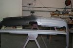
Rear Bumper Showing Lower Fixing Points84 views
|
|
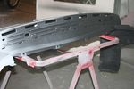
Rear Bumper High Build Primer & Showing Tread Plate Removed & Fixing Points Top85 views
|
|

Howe Sound11 viewsHeading up Bromme ridge, View of Squamish and Howe Sound
|
|

Howe Sound10 viewsView of Squamish and Howe sound
|
|

How to remove spring stuck behind ashtray12 views
|
|

New HSE LUX63 viewsMy new Discovery 4 HSE Luxury in the showroom at Hunters of Chester, this was taken earlier today before she went to the workshop to have the side steps fitted, collection is lunch time Friday...can't wait now.
|
|

outside the showroom on collection day58 viewsIts all mine....at last
|
|
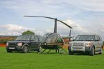
CALENDER ENTRY 2010269 viewsTaken at Nailsea flower show. I drove my disco there then Frapp took me to the airport to collect the helicopter. I flew the choper in and Frapp drove back there. Guess who arrived first!
|
|
48 viewsA single pin in the headrest screens was pushed in, meaning the screens would power up, but no picture would show.
|
|

Thule 9705 plate40 viewsShows how the fixing plate reduces the departure angle
|
|
Modified Thule 9705 plate42 viewsShows the adapter plate after modification to improve departure angle
|
|
TMC amp location showing antenna button68 views
|
|
how deep?91 views
|
|
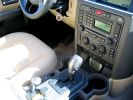
I have the screen lightly wedged between the rubber mat and the bottom of the ashtray567 viewsI plan to create a wooden block to attach the screen to and use foam tape (sticky on both sides) to hold it in. However, so far it hasn\'t moved and the ashtray is completely useable (for my parking meter quarters).
|
|
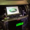
IHU and TSD14 viewsShowing boot up sequence
|
|
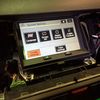
Touch Screen Display Unit13 viewsShowing menu screen shot
|
|
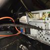
Rear of Touch Screen Display Unit13 viewsShowing connections in place
|
|
Rear of Touch Screen Display Unit10 viewsShowing details and connections
|
|
IHU and screen12 viewsShown with screen MOST looped out
|
|

New pump showing reinforced casting of the tensioner mount13 views
|
|

New pump showing reinforced casting of the tensioner mount10 views
|
|
How to get a leaking seal out without causing damage11 views
|
|
Richard showing some leg296 views
|
|
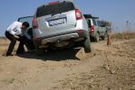
Shows you how good the D3's articulation is in comparison281 views
|
|
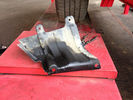
this is how the underbody looks like with my old intercooler hose10 views
|
|

Interstate Battery Dimension sheet641 viewsThis sheet is hard to find - the sheet is not on the Interstate corporate web site but some dealer web sites display it. The pdf shows most of their available batteries including the H7 and H8 sizes that are the LR North America replacement batteries for the main starting battery. These batteries are of the Land Rover desired "shallow" cycle high discharge current Maintenance Free, (Ca Ca), internal construction, (not AGM, but instead, Wet Flooded Lead Acid with battery "caps" and Ca grid separators).
For the AUX battery , the H6, (BCI Group 48), is probably similar in dimensions to the Varta E12V75N that is popular in Australia. For that battery to fit in the second battery compartment, you must grind out the angled nibs on the inside front bottom of the LR black plastic surround, something I did wish to do and hence installed a Group 40R on a spacer. Alternately, one can choose an Interstate BCI Group 47 which is similar to a DIN H5 for the AUX location. I did this when I had to replace my 40R. No vertical spacer is required and the stock battery tie down bolts and clamp work well.
|
|

iPad holder17 viewsHow to mount/ demount the iPad holder.
|
|

JAE connectors for the upper hatch switch and FAKRA connectors for the Sat NAV.539 viewsThis jpg shows some catalog pages listing the MX19 connectors used on the upper hatch switch.
Also shown are the FAKRA connectors that are used on the rear of the Sat NAV.
|
|

Replacement switch from RRS installed on LR3864 viewsThe switch shown is LR part number YUZ500020, the upper rear hatch release switch that is found on the Range Rover Sport.
The switch body is the same switch as on the LR3 except that there is no wiring disconnect on the LR3. Hence when the switch corrodes and requires replacement, the LR solution is to purchase a new handle and license plate light assembly. I instead cut off the old switch and installed a JAE mating connector to the existing wiring and hence just plugged the RRS switch in.
The replacement RRS switch snaps into the same rectangular space in the same manner as the removed LR3 switch, the difference is the JAE male wiring connector.
|
|

36 views
|
|

Thread upload8 viewsImage uploaded in new thread
|
|
| 651 files on 2 page(s) |
 |
1 |  |
|