| Search results - "lock" |
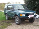
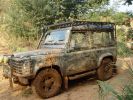
51 viewsD44 front winch bumper. Ali washer bottle. D44 rear h/d bumper. centre diff lock. 235x85x16 pirelli muds. OME +2" springs & shocks. front diff guard. side tree bars. wired for roof CB. Aux fuse block. safari snorkel. extended wading tubes. the list goes on...
|
|

Offroad Training in Linthe, Germany.208 views9 Cars: Suzuki Jimny; Touareg V10 Diesel no difflock; Touareg V6 Diesel rear difflock; Disco 1; Disco 2; Disco 3; RR ´05; RR ´06; Q7.
|
|
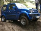
200 viewsSuzuki Jimny. Some holes were deep enough to swallow the little fella, but it got out as long as all wheels were on the ground. No difflocks or electronics in this one.
|
|
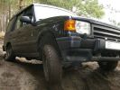
199 viewsSuspension working nicely. Thia model has no difflocks - not to mention electronics - to control wheel spin, so it needed speed to get through some points.
|
|
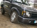
216 viewsDiscovery 2. Can´t remember if it had any locks or electronics.
|
|
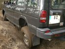
209 viewsDiscovery 1. Is stuck in this picture. No difflock.
|
|
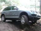
223 viewsThis is the Touareg with the 6cyl engine and rear difflock. did well, useless air-suspension though.
|
|
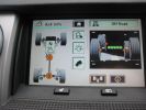
both diff locks active 251 views
|
|
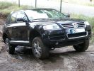
241 viewsThis Toureg is stuck - doesn´t look like it. After 8 hours of driving everyone agreed that with the big 10cyl. diesel engine you should probably oder the rear difflock as well... In this picture the rear left anf front right wheels have no grip, esp or whatever just doesn´t do it.
|
|
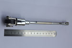
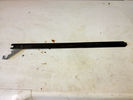
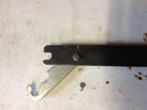
109 viewsFinished adapter ready to be locked in
|
|
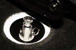
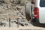
130 viewsspare wheel winch adater locked in position
|
|
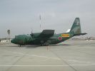
Club AC-130150 views
|
|
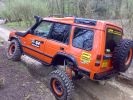
COVER SHOT FOR TOTAL OFF ROAD114 viewsG WAGEN AXELS FITTED WITH HYDRAULIC FRONT + REAR DIFF LOCKS + EXTREAM SUSPENSION SYSTEM FRONT + REAR WARN WINCHES.
|
|
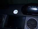
Clock in Dash104 views45%
|
|

pic of lock and key50 views
|
|

Llamsrecovery mode installation53 viewsSpring lock inconspicuous
|
|

Radio location539 viewsMy remote head UHF CB mounted on the front of the ashtray, ham HF/VHF/UHF remote head radio mounted on a block in the coin tray and my GPS on a turned wooden block in the cup holder. Both radios are under tha driver and passenger seat and the antenna for the GPS is suction mounted inside the windscreen.
|
|

Lock mechanism removed from tailgate131 views
|
|

Local WA newspaper article on D3 Theft168 viewsThe article is info by police public affairs. They wanted something to keep people locking doors and taking care during the holiday period. There are also TV public service announcements on air in WA featuring my wife confessing to leaving 1 door unlocked leading to the theft.
|
|
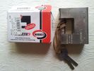
Corbin grizzly high tensile steel lock34 views
|
|
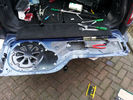
Tailgate Lock failure and repair276 views
|
|
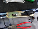
Tailgate Lock failure and repair105 views
|
|
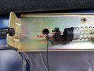
Tailgate Lock failure and repair101 views
|
|
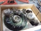
Locking Kit637 viewsready to install
Mfd from https://www.facebook.com/DifferentialPartsUS
|
|

clock in chiang rai15 views
|
|
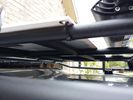
solar panel install356 viewsAt least at this point, I mounted it by using Clear Silicone RTV. This stuff is kind of like glue, but can be removed. If it doesn't hold up after curing and driving, I'll remove it and come up with another plan. I used heavy cable ties on the 4 grommets, in case it lets loose, it won't take out my wiring and the car behind me. 2 Panels are dandy like this, but I don't want to permanently block the roof space. Grape Solar to power my snomaster fridge
|
|

before hair cut10 viewsFlock before shearing
|
|
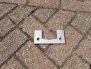
Locking Plate5 views
|
|

Lock22 views
|
|

Lock12 views
|
|
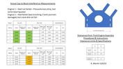
Thread upload7 viewsImage uploaded in thread 203917
|
|

Thread upload12 viewsImage uploaded in thread 203917
|
|
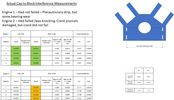
Thread upload8 viewsImage uploaded in thread 203917
|
|

Anti Lock and Traction Control description and operation.1986 viewsNote on page 6 of this 17 page pdf the significance of the Steering Angle sensor mounted on the steering wheel shaft. The paragraph regarding the plausibility check as related to the brake pedal being not depressed is why the clean operation of the second set of contacts on the brake switch matters so much.
|
|

D4MY2012 Clock Spring119 viewsD4MY2012 Clock Spring
|
|

Steering Column detailing Steering Angle Sensor1496 viewsItem 2 in the picture on page 1 of the 9 page pdf shows the location of the steering wheel sensor. Page 5 of the pdf has a paragraph describing the operation of the sensor. When the steering wheel does not point the same direction as the real wheels, then the computers can put the 3 into safe mode and down goes the suspension. See also the 17 page pdf on the Anti Lock and Traction Control pdf.
|
|
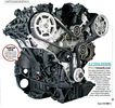
Thread upload3 viewsImage uploaded in thread 198799
|
|
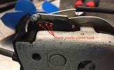
Close-up of lock showing emergency cable and pared back plastic tab141 views
|
|
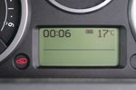
Thread upload18 viewsImage uploaded in new thread
|
|
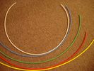
6mm Heat Shrink colours 362 viewsI decided to colour code the tubing so I used 6mm electrical heat shrink.
As there is no apparent colour coding re the 3, I tried to emulate the P38 coding; #1 LR red, #2 RR blue, #3 LF yellow, and #4 RF green. This was not doable as both left side air springs have green coloured tubing coming off the top of the front and rear air springs. I therefore arbitrarily chose the Left Rear to be red; Left Front green; Right Front yellow; Right Rear blue; and for the air compressor supply line, White coloured heat shrink. Since two new lines tie into each air spring line, I made the line between the air spring and the FASKIT, a single solid colour, and the line from the FASKIT to the valve block, White, plus the related appropriate solid colour.
|
|

Shift Lock Solenoid Problems14 viewsHow to repair and/or get home when the solenoid fails
|
|
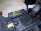
Ham Radio454 viewsThe remote head of the Icom IC706 mounted on a block of wood shaped to fit the coin holder. This is an HF, VHF and UHV transceiver.
|
|

anti lock control40 views
|
|
269 views
|
|

231 views
|
|

B0llocks.com36 views
|
|

Beer O\'Clock40 views
|
|

Crazy Paving67 viewsThe last place you would expect to find a nice bit of block paving. The 513m summit of Monkside on the DISCO3.CO.UK Kielder day 2009.
|
|

83 views
|
|

142 views
|
|

135 views
|
|
22 views
|
|
LPFP GAUZE15 views
|
|
Thread upload6 viewsImage uploaded in thread 194659
|
|

Thread upload9 viewsImage uploaded in thread 83208
|
|

Thread upload4 viewsImage uploaded in new thread
|
|
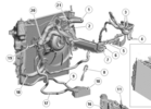
Thread upload30 viewsImage uploaded in thread 105366
|
|
Thread upload10 viewsImage uploaded in thread 199158
|
|
Thread upload13 viewsImage uploaded in thread 199158
|
|

Thread upload8 viewsImage uploaded in new thread
|
|
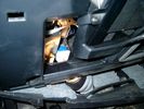
Brake Switch Visible thru Opening4973 viewsThe blue and white bit is the switch; the sort of gold appearing box,(it is really black), you will not see in your 3 as it is a Smooth Talker brand amplifier for my Blackberry phone antenna. This install is detailed in the SmoothTalker phone antenna section of my gallery.
One way to remove and install the switch is to lower the "horizontal" panel above the brake pedal as shown where the flashlight head is located. To actually remove the switch, you slide your hand thru the gap and rotate the switch clockwise 1/4 turn while watching thru the rectangular opening. Installation of the new switch is the reverse of above - 1/4 turn counterclockwise.
Before you remove the switch, note its orientation - horizontal with electrical wires to the left. That is the way it should look after replacement as well.
The second time I replaced the switch, I did it all thru the rectangular opening and did not remove the horizontal panel - that is experience helping out.
The knee kick you have to remove regardless. It is sort of hinged at the bottom so you just pull at the top and sort of rotate the knee panel and then pull upwards for two plastic "fingers" to clear the slots they reside in.
|
|
Thread upload1 viewsImage uploaded in new thread
|
|
Thread upload1 viewsImage uploaded in new thread
|
|
Thread upload3 viewsImage uploaded in new thread
|
|
Cam Shaft Locking Pin93 views
|
|

Camshaft Locking Tool58 views
|
|

can-lockguide34 views
|
|

Can Bus14 views0s - Start of trace
5s - unlock 1
10s - ignition on (In-I-II)
30s - ignition off (II-I-Out)
Non accurate timings - +/- ~2s.
|
|

101 views
|
|

73 viewsMS excel sheet for monthly mileage report will give average fuel consumption.(most cells have formulas to help fill in from previous line)
on first sheet add details you want on monthly sheets. during use the data needed to be added is ending reading on clock, places visited (if you want).
how much fuel when you purchased it also fuel in tank at start and end of month
|
|

Central Door Locking Operation Description1458 viewsThis 17 page pdf explains how the door locks are supposed to operate. Note that on page 9/17, the explanation of the operation of the hood ajar switch is wrong. It operates similar to the door and tailgate ajar switches; that is when a "door" is closed, the switch is closed to maintain a ground back to the CJB. Opening the hood, door, or tailgate removes the ground breaking the circuit and hence allows for an alarm condition.
|
|

Thread upload37 viewsImage uploaded via thread
|
|
Thread upload37 viewsImage uploaded via thread
|
|

C2658 locking bar42 views
|
|
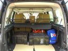
Load space368 viewsShows the SA Front Runner Wolfpack stacking plastic storage boxes that I keep laod straps etc in and the 2nd is tool kit, spare belts, jerry can funnel and tools, plus airline and tyre inflator/deflaotr for ARB on-board compressor, HD jump leads. ARB Winch pack (Orange)with strops, snatch blocks, shackles, gloves, and 2 ARB recovery dampers. Really great 4x4 1st Aid kit from Outdoors warehouse in SA. LRs own loadspace guard - not the best design if you want to store a long load. Mods to be carried out!
|
|
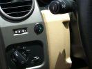
Long Ranger auxilairy fuel tank pump switch and tank gauge308 viewsFitted to the right of the air vent thumbwheel, the neat combination switch and gauge take sup no room at all. Switch locks on or off, but no pump running warning lamp! Contents of the tank are indicated by 5 LEDS, 4 green and 1 red for full, 3/4, 1/2, 1/4 and empty. Pump transfer rate of just 2 litres p/min is disappointing. I transfer on the move when main tank is at 1/4.
|
|

192 views
|
|

169 views
|
|
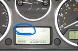
Thread upload7 viewsImage uploaded in new thread
|
|

Thread upload43 viewsImage uploaded in thread 164028
|
|

clock45 views
|
|

Thread upload5 viewsImage uploaded in thread 125594
|
|

Thread upload5 viewsImage uploaded in thread 146269
|
|

Thread upload6 viewsImage uploaded in thread 200758
|
|
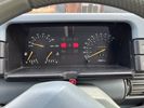
Thread upload4 viewsImage uploaded in thread 207823
|
|
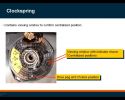
334 views
|
|
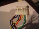
Clock Spring / Rotary Coupler Connector from horn controls209 views
|
|
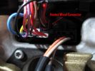
385 views
|
|

Thread upload2 viewsImage uploaded in thread 179494
|
|

Thread upload1 viewsImage uploaded in thread 209420
|
|
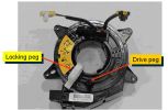
313 views
|
|

64 views
|
|

31 views
|
|
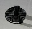
3D Printed Clock Spring27 views
|
|

7 views
|
|

34 views
|
|
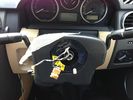
31 views
|
|
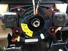
30 views
|
|
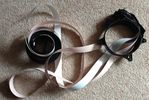
42 views
|
|

Thread upload6 viewsImage uploaded in thread 152509
|
|

Thread upload2 viewsImage uploaded in new thread
|
|

200 views
|
|
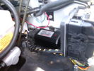
CounterAct Power Supply mounted 246 viewsPicture is blurred, however power supply is 3M two sided tape to the flat black plastic of the second battery compartment just under the antilock brake pipes to the fender side of the brake fluid reservoir. The white wire to the left rear coupler pad runs thru the firewall hole near the steering column. The blue wire to the right front coupler runs across and above the engine following the other wiring looms that cross the vehicle.
|
|
Thread upload13 viewsImage uploaded in thread 128829
|
|

Thread upload10 viewsImage uploaded in thread 128829
|
|

Alloy Wheel Locking Nut Key254 views
|
|

Alloy Wheel Locking Nut Key258 views
|
|
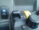
ARB Front Locker in Disco3111 viewsA bit of a challenge for the installer since it was the first they had done but all done and nice and tidy.
|
|
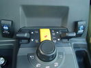
ARB Front Locker in Disco3117 viewsA bit of a challenge for the installer since it was the first they had done but all done and nice and tidy.
|
|
Thread upload32 viewsImage uploaded in thread 41187
|
|
Thread upload20 viewsImage uploaded in thread 139852
|
|
Thread upload11 viewsImage uploaded in thread 159659
|
|
Thread upload16 viewsImage uploaded in thread 185241
|
|
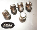
Thread upload3 viewsImage uploaded in new thread
|
|
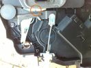
Thread upload11 viewsImage uploaded in thread 3376
|
|
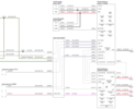
D4_clockspring_1.png23 views
|
|
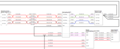
D4_clockspring_2.png23 views
|
|

Thread upload12 viewsImage uploaded in new thread
|
|

Thread upload1 viewsImage uploaded in thread 206131
|
|

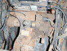
D3 reqar diff lock186 viewsView from right rear tyre well, left rear tire/rim visible on other side. Actuator motor visible
|
|

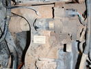
Difflock225 viewsDifflock with annotations
|
|
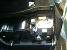
199 viewslocating of resistor to rear of D4 led lights and scotch blocks but theres loads of room so the choice is yours
|
|
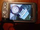
190 views
|
|

184 views
|
|

about 12 miles on the clock!255 views
|
|
Thread upload4 viewsImage uploaded in thread 127619
|
|
Thread upload8 viewsImage uploaded in thread 127619
|
|
Thread upload5 viewsImage uploaded in thread 127619
|
|
Thread upload5 viewsImage uploaded in thread 127619
|
|
Thread upload4 viewsImage uploaded in thread 127619
|
|

45 views
|
|

Thread upload2 viewsImage uploaded in new thread
|
|

Thread upload1 viewsImage uploaded in thread 181232
|
|

Thread upload1 viewsImage uploaded in new thread
|
|

Thread upload2 viewsImage uploaded in new thread
|
|

05 plate disco47 viewsover 120k on the clock leather damaged, guys wanted over 12k, said it had full farnell dealer service. mmm i think not, as checked
|
|

Thread upload21 viewsImage uploaded in thread 134702
|
|

Door Lock Cylinder223 views
|
|
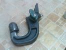
Tow bar in the locking position166 views
|
|
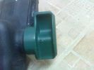
locking pin151 views
|
|
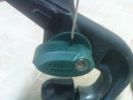
knock the locking pin downside with a small screwdriver170 views
|
|
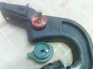
Lock and lever removed169 views
|
|
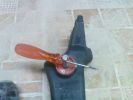
Put the screw driver into the hole then pull and turn to unlock160 views
|
|
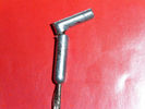
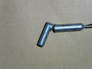
Small rod broken, note the small locking pin broken also169 views
|
|

Now you can unlock the tow bar without a key171 views
|
|
Blocked Intercooler222 views
|
|

Lead Car Entering the Finish116 views7 May 2007 - My D3 on duty as lead car in shinfield 10K road race. what a nightmare driving at low speed in the rain. Clock was mounted on standard crossbars. connection to additional batteries in boot cable thru side window. There is a small offroad section (actually an un-made road) Oaklands Road, Shinfield, Reading (suggest anyone test driving in the Reading area take this road)
|
|
cam shaft locking tool53 views
|
|
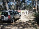
Locked gate and wire rope fence at start of Limeburners.68 views$11,000 fine if you are caught in a vehicle on the other side!
|
|

44 gallon drum - blocking entry to a cave58 views
|
|
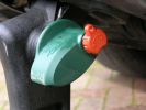
Fuel tank cap with key lock68 views
|
|
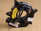
D3 Clockspring Unheated42 views
|
|
rear diff lock motor 1128 views
|
|
rear diff lock motor122 views
|
|
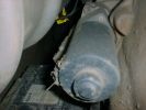
rear diff lock motor 2130 views
|
|
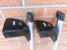
Side on of feet and bar locking knobs.21 views
|
|
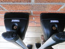
Showing Thule locks21 views
|
|
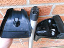
Security cover off showing lock.22 views
|
|

188 viewsMt Skene - 3 hours NE from Melbourne, Victoria. One of the few accessible but mostly snow-blocked alpine roads in Victoria\'s "high" country, that doesn\'t lead to a resort (and get cleared).
|
|
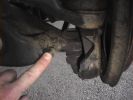
Lock Stop. Grease to stop the graunch.894 views
|
|

Thread upload4 viewsImage uploaded in thread 206131
|
|

Emergency unlocking46 views
|
|

34 views
|
|
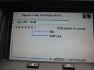
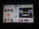
speed lock config - locked235 views
|
|
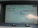
speed lock config - unlocked233 views
|
|

6 views
|
|

9 views
|
|

Thread upload1 viewsImage uploaded in thread 198799
|
|

Loch Locky161 views
|
|

164 views
|
|

Thread upload2 viewsImage uploaded in thread 198799
|
|

Thread upload18 viewsImage uploaded in thread 200211
|
|

Thread upload7 viewsImage uploaded in thread 124445
|
|

Fuel flap locking system missing bit21 views
|
|
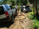
Winch/snatch block113 viewsThis picture shows the winch in position.
|
|

75 views
|
|
Thread upload8 viewsImage uploaded in thread 150734
|
|
Thread upload6 viewsImage uploaded in thread 133043
|
|

Thread upload2 viewsImage uploaded in new thread
|
|

Thread upload4 viewsImage uploaded in new thread
|
|

handles locks latches and entry systems41 views
|
|
Thread upload3 viewsImage uploaded in new thread
|
|
Thread upload21 viewsImage uploaded in new thread
|
|
South end view of Lock Ness146 views
|
|
Well, there wasn\'t a lock on the gate ???149 views
|
|

Thread upload2 viewsImage uploaded in thread 204567
|
|

Thread upload3 viewsImage uploaded in thread 204567
|
|
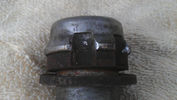
Locker intact32 views
|
|
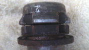
Locker starting to sepreate25 views
|
|
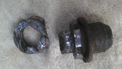
Locker in pieces31 views
|
|
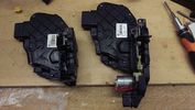
6 views
standard to keyless door lock actuators
|
|
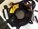
Clock Spring12 viewsImage uploaded in thread 100073
|
|
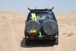
View the Nissans saw106 viewsRecovery strap pre-shackled to the rear recovery eye and secured with a bungey strap to the rear door ladder saves a lot of time when running against the clock - and having to recover a bogged in Nissan!
|
|

66 viewshave a look the range on the clock
|
|
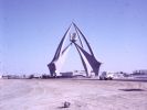
Dubai Clock Tower 196680 views
|
|

Dubai Clock Tower Today71 views
|
|
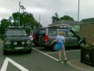
The Block In107 views
|
|
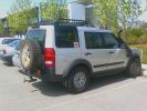
Opposite Lock spare wheel carrier740 views
|
|
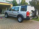
Opposite Lock spare wheel carrier + Dynamic 4x4 steel 17" wheels745 views
|
|

Locking wheel nut4 views
|
|
NSF left connection blocks28 views
|
|

D4 locking 324 views
|
|

D4 locking 215 views
|
|

D4 locking 119 views
|
|

Plockton68 views
|
|

Duff block paving39 views
|
|

D2 clocks 39 views
|
|

D2 Clocks rear10 views
|
|

D2 clocks front7 views
|
|
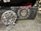
Crank Locking tool23 views
|
|
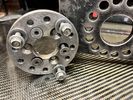
Crank Locking tool21 views
|
|
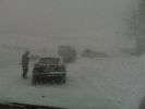
Blocked route to Mnt Blan tunnel due to snow / slipping wagons178 views
|
|
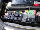
Picture of the engine compartment fuse panel5779 viewsEngine compartment fuse panel located near the battery. This is where F3E, (5 amp), F26E, (20 amp), Fuseable link 10E, (60 amp) and Relay 7E, the now upgraded 70 amp air compressor motor relay, part number YWB500220, (E is for Engine compartment fuse box), are all located. Fuse F35P, (5 amp), is inside the Passenger compartment behind the lower glove box door.
To keep the suspension from going down to the stops when driving, (or parked), it appears that it is only really necessary to remove F26E to depower the exhaust valve and generally keep all the valve block solenoid valves in a closed position trapping whatever air is within the air springs. F3E gets its power thru F26E, so when F26E is removed, the F3E circuit is automatically de-powered. F35P is more interesting in that battery power goes thru the ignition switch and F35P and then into the air suspension control unit. Apparently however, if F26E is removed, removing the F35P is not needed even when the engine is running.
With all fuses still in, if you have a problem, in practice, ideally, the compressor still works and will raise the 3 to an appropriate height. If so, one can then shut the engine off and allow the computers to go to sleep and then you remove the fuse(s). In actual practice, it seems that one need only pull the F26E fuse and can do so with the engine running. All the same, one might consider that the 3 is first a mobile computer, and secondly a 4x4. Computers prefer to go to sleep before the plug is pulled on them, however given that F26E circuit is always alive, then the computer never sleeps. With the fuse(s) pulled, and if you are still up, you can now be a 4x4 instead of a low rider. The whole purpose of the fuse pulling exercise is to depower the one and only system exhaust valve that is physically located within the compressor unit, (to keep it from opening), and secondarily to keep closed the four air spring solenoids within the block valves. This also shuts the air compressor down and stops the air compressor from making air even if the compressor is still good. That is why you initially need the fuse(s) in to allow the compressor to make air if it can.
|
|

Switch is blue colour thing thru the rectangular opening.3177 viewsThe blue coloured plastic bit thru the rectangular opening is the brake light switch. The fist time, I found it easier remove the switch by dropping the horizontal plastic panel, (two screws), and then slipping my hand in and rotating the switch clockwise 1/4 turn. The second time, I was able to remove the switch thru the rectangular opening and did not need to remove the horizontal lower panel. Obviously, I had to remove the sloping knee pad panel, (note sort of hinged at the bottom so pull back from the top.)
Regardless, do not touch the brake pedal - just let it sit where it wants to. One has to first remove the angled knee pad panel that sits under the steering wheel. It can be pulled from the top corner at the door side. Pulling releases a pair of those U shaped metal clips that LR loves so dearly. You have to pull quite hard. The bottom is held by a couple of plastic fingers in a couple of slots so you pull at the top till the two clips release and then rotate the panel and pull upwards a bit.
To remove the switch, you rotate it clockwise and pull outwards. Rotating the switch clockwise automatically retracts the plunger back into the switch body away from the brake pedal arm.
Similarly when you install the new switch, the required 1/4 turn anti clockwise rotation action releases the plunger so it lays up against the brake pedal arm and at the same time, secures the switch in place.
To remove the electrical wires, the switch will drop below the horizontal pad and hang from the wires so unclipping the electrical connector plug is fairly easy to do.
|
|
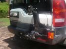
Broken Rear Wheel Carrier197 viewsThe Opposite Lock rear wheel carrier. Vertical weld adjacent to brake light has broken
|
|

Broken Rear Wheel Carrier166 viewsOpposite Lock rear wheel carrier 7 months old, one outback trip. Weld has broken. OL replaced with new improved unit free of charge (has just covered 20000 klm of outback roads without problem)
|
|
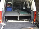
Opposite Lock Drawer system212 views
|
|
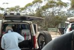
Southern end of Googs Track Sept 2007131 viewsOpposite Lock Rear Wheel Carrier, Opposite Lock Drawer System
|
|
Bararranna Gorge Gammon Ranges Sept 2007163 viewsOpposite lock Rear Wheel Carrier and UHF antenna
|
|
Fan pulley Locking tool71 views
|
|
Fan pulley Locking tool74 views
|
|

blocked99 views
|
|
diff lock142 views
|
|

Wiring fault189 viewsThe wire and connector that corrodes causing a fault to the key fob locking
|
|

107 viewsMassingir dam wall, with winches for manual opening of locks in back ground.
|
|

The clips (one completely broken, one partially, and one ok) that hold the plastic locking mechanism to the camera.31 views
|
|
Clock spring39 views
|
|
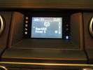
D4 Lowest Grade Radio - Screen Closeup72 viewsThe monochrome screen with colour-lit icons on the left to indicate source, and bluetooth icon on the right to indicate connectivity. There are also two hardware buttons for hour/minute clock setting.
|
|
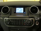
D4 Lowest Grade Radio - Wide Angle76 viewsThe CD player is at the bottom of the picture, the control buttons in the middle, and at the top is the screen with colour-lit icons on the left to indicate source, and bluetooth icon on the right to indicate connectivity. There are also two hardware buttons for hour/minute clock setting.
|
|

Internal heating element fastend with 3M Dual Lock 44 views
|
|
Hitch Receiver locking pin13 views
|
|

Boot Lock actuator21 viewsBoot lock actuator
|
|

Ken Blocks Stunt Motor (as seen on top gear)40 views
|
|

Locking tabs have lost their grib on the loom29 views
|
|
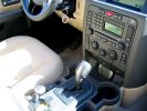
I have the screen lightly wedged between the rubber mat and the bottom of the ashtray567 viewsI plan to create a wooden block to attach the screen to and use foam tape (sticky on both sides) to hold it in. However, so far it hasn\'t moved and the ashtray is completely useable (for my parking meter quarters).
|
|
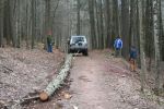
blocking damaged trails132 views
|
|

blocking damaged trails133 views
|
|

Boulder Pull198 viewsRubber Ducky helping the forest rangers block an off-limits section in George Washington National Forest.
|
|

Boulder Pull150 viewsRubber Ducky helping the forest rangers block an off-limits area in George Washington National Forest.
|
|

LRO18556 Clock spring and indicator/wiper stalk30 views
|
|

Flywheel locking tool in place11 views
|
|
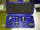
Britpart cambelt locking kit9 views
|
|
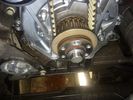
Important to add the + 90 deg marked at 12 o'clock to assist10 views
|
|
ISOLOCK42 viewsIsolocks and Isolock PCB's
|
|

Thread upload20 viewsImage uploaded in thread 131211
|
|
Ken Block27 views
|
|
Ken Block Gopro23 views
|
|

Ken Block26 views
|
|

Ken Block Gopro22 views
|
|

Key in Ignition Electrical Wiring Diagram1051 viewsThis shows the key in ignition wiring, (LGW, 1.5D), running from the key lock cylinder to the Central Junction Box, (CJB), thru 5 amp fuse F40P, located in the fuse box behind the lower glove box door.
You can remove the 5 amp fuse and the good news is that the ignition chime will not sound any longer; the bad news is that a bunch of other circuits that rely on knowing if the key is in or out no longer work.
Also note the Transponder Coil D219 reference.
|
|

LA501-023 - Technical Bulletin - Child Lock Cam Service Part Replacement Procedure63 views
|
|
1000 MILES ON THE CLOCK112 views
|
|
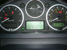
New clocks and dials1298 views
|
|

Thread upload1 viewsImage uploaded in thread 203364
|
|

10 views
|
|

Upper tailgate lock / cable31 views
|
|

Thread upload6 viewsImage uploaded in thread 143766
|
|

Thread upload12 viewsImage uploaded in thread 148203
|
|

Thread upload17 viewsImage uploaded in thread 204678
|
|

Thread upload10 viewsImage uploaded in thread 187407
|
|

Thread upload4 viewsImage uploaded in thread 187407
|
|

Thread upload4 viewsImage uploaded in new thread
|
|
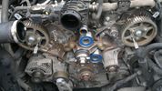
Locked camms22 views
|
|
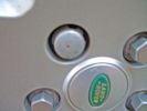
Which locking wheel nut57 views
|
|
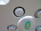
Which locking wheel nuts79 views
|
|

Which locking wheel nut? help60 views
|
|

Which locking wheel nuts?!78 views
|
|

48 views
|
|
Thread upload4 viewsImage uploaded in new thread
|
|
244 views
|
|

Locking system - Evqoue76 views
|
|
Thread upload8 viewsImage uploaded in thread 201763
|
|
Broken Locking Wheel Nut19 views
|
|

Thread upload1 viewsImage uploaded in thread 205937
|
|
Thread upload14 viewsImage uploaded in new thread
|
|
Thread upload12 viewsImage uploaded in thread 149551
|
|

Thread upload11 viewsImage uploaded in thread 111528
|
|

Lock Diag40 views
|
|
Thread upload1 viewsImage uploaded in new thread
|
|
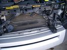
19mm wiring loom in trough behind bumper and in front of rad792 viewsThe 19mm wiring loom is large enough that a maximum of six 6mm air lines can be fished thru as required. The loom runs from the FASKIT panel located in the engine compartment behind the left front headlight, down and across in front of the rad and then down to the front axle valve block located behind and below the right fog light.
|
|
Block Diagram of Disco 3 / LR3 Air Suspension System.1552 views
|
|

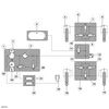
Air System Schematic with parts identified.1374 viewsAir system block diagram with components numbered and identified.
|
|

Battery Maintainer pigtail sticking out of Grill726 viewsThis is all you see when everything is put back together - just the pigtail and Weather Pack blanking plug. Most often, I have it all tucked back behind the grill.
In winter, there may be a second cord hanging out as well - the 120 VAC power cord for the engine block heater, a tea kettle like element inserted in the engine block. NAS petrol V8's do not have the Fuel Burning Heater, (FBH), installed, but instead in cold area markets have the block heater element assembly available as a dealer installed option. There is an argument to say that the heating element is factory installed in all cold climate V8 gasoline engines, however the appropriate power cord is not. If true, this means that all one needs to purchase is the area specific power cord and plugging in / attachment to the engine block located block heater.
As such, you will often see a conventional 120VAC three prong power plug hanging loose out of the grill of most vehicles here in the wintertime. In summer, most drivers tuck the plug back behind the grill as it is no beauty mark.
|
|
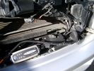
Battery Maintainer switching box plug and CTEK Multi US 3300 charger. 706 viewsThe CTEK Multi US 3300 maintainer is just sitting there for the picture. In addition to topping up both batteries, the CTEK can provide power such that if the batteries were completely dead, there would be power to the door locks and hence, one could most likely still gain access via the remote once the starting battery charged up a bit.
The Land Rover recommended method is via the hidden key hole which is mechanical, however that presumes the mechanism is not frozen from lack of use. As such, the manual lock should be exercised at least once a year to ensure that it still functions.
The blanking plug sitting on top of the plastic box is of the GM Weather Pack series. That is what I like to use for vehicle wiring that is subject to moisture, (or not).
|
|
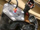
Compressor Electrical Plugs 1406 viewsThis shows the two electrical connectors; the two pronger is the power to the compressor, and the multi-pin connector carries control signals. Also the temporary red plug is where the 6 mm tubing from the centre valve block connects. This line carries both the compressor and exhaust air to and from the springs.
|
|
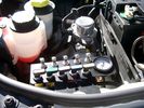
View of mounted panel from front left side877 viewsNote that all valve handles are shown in the OFF position, (the trouble position). In this case, the air that is in the air springs, (if any), is trapped in there - that is the valve blocks cannot vent whatever air is already in the air springs as the air lines between the springs and respective valve blocks are closed off by the FASKIT valves. In operation, there may be only trouble with one air spring, (perhaps a wheel height sensor), and as such, only one valve would need to be closed. If there was complete air compressor failure, then all valves would be closed and then as required, each spring could be manually filled from an outside clean dry oil free air source.
|
|
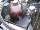
Empty space in NAS LR3 for location of FASKIT panel599 viewsThe empty space is available as the North America Spec gasoline engine LR3's do not have the Fuel Burning Heater installed. The air lines from the four air springs and the air tank will appear to rise up from under the headlight assembly. The lines to the front block valve assembly located behind the front right fog light will sort of run within the bumper across the front of the radiator down into behind the righthand fog light. The rear lines somewhat follow the path of the existing air feed line from the front valve assembly to compressor. Rather than be located between the left front fender liner and left metal wing however, the four lines will feed thru the empty wing space inside and above the wheel well arch and exit down by the left front mud flap. From there, the lines run along the left frame member above the air tank and then parallel the frame over top the compressor to the top of the rear left air spring where the rear air block valve assembly is located.
|
|
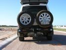
kaymay rear bumper/tire carrier493 viewsthis is on delivery to me.... ;) . it went on easily but i will have it modified to place right wheel more toward middle like disco II. i will only ever use the laft side for jerry can or something, not another tire. i don't like how right tire totally blocks main lamp.
|
|
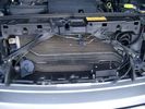
Plastic cover and Box back on in Front of Radiator 637 viewsThe wiring loom is below the cover - nothing is crushed or distorted and all fits back together OK. The black plastic box with the DPDT, (centre OFF), toggle switch is to tie the battery maintainer to each of the two batteries per the Traxide Dual battery install. I can also get power to the power door locks if all fails.
|
|
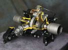
Rear Differential cutaway with E-Locker 1210 viewsThis jpg is from the link below.
There are another ten or so cutaways plus a whole file group showing a 2005 LR3 sectioned for the 2005 Chicago Auto show. Each jpg has an enlarge function to the bottom right of a main picture.
On one jpg you can see right into the stepper motor.
http://www.cutawaycreations.com/cutaways.php?project=land-rover-electronic-rear-differential#/IMAGES/car4/images/image1.jpg
Both the front and rear differentials are manufactured by Dana Spicer in the UK. Dana calls them a Clamshell design.
|
|

LR3 Electrochromatic Interior Rear View Mirror wiring diagram.852 viewsIt seems that there are two fuses, F69P and F5P that provide power for the interior rear view mirror. Ten amp F5P is a feed off the reverse gear relay and inhibits auto dimming when reverse is selected. Five amp F69P provides power to the auto dimming circuits and the garage door opener function if optioned.
The pdf can be downloaded and printed out. For on screen viewing, right click on the pdf and select the Rotate Clockwise button.
|
|
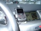
Blackberry Tour mounted on air vent showing default analogue clock 213 viewsA characteristic of the Blackberry is that when charging, the display can default to an analogue clock. Hence when the unit sits in the holder, the phone is being charged and the analogue clock displays. When the phone rings, the clock disappears and the call id displays.
|
|
19 mm wire, (tubing), loom rising from below at left headlight657 viewsFrom the FASKIT panel, five air lines fit in the 3/4" (19mm) wiring loom and feed to the front air valve block located behind and under the right front fog light.
|
|
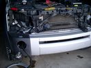
Wiring, (tubing), loom exiting temporarily from the front right fog light.569 viewsThe front axle air valve block is located just behind and below the fog light. Access to the valve block is by removing the right front fender liner, (or the bumper). The FASKIT lines are attached to the left and right front air spring lines at this location; also compressor air is taken from this location as well. Cutting the lines at as few different locations makes it easier to find leaks at a later date. As above, five 6mm air lines run from the FASKIT panel to the front axle air valve assembly and run within the loom. Two pair of the lines are for control of the air springs, and the fifth line taps the air supply at the valve block assembly off the compressor. This will be the air source line rather than tapping in directly to the high pressure air tank.
|
|

lr3-kaymar-closed with 20"405 viewsthe kaymar carrier, designed to allow two tires, sets them both a bit outboard, thus blocking the lamp. that\'s when I realized why they put the fully functional lamps in the bumper (functions: running, brakes, signals, hazard)
I plan to re-weld the locating section more towards the middle of the rear similar to Disco II orrientation.
|
|

solo steep gravel stop = park brake plus reverse on shifter333 viewsso our disco II\'s locked all 4 wheels with brake but now the modern lr3 slides away with only the park brake!!!! 1. put auto shifter in reverse (low gear) with foot on brake, 2. apply park brake, 3. get out and snap photo incase something fails and it slides away ;)
I reversed up the hill from this position, system decided to engage extended heigh mode for some reason trying to gain traction on loose surface.
|
|

LR3 AJV8 block heater location639 viewsThis 1 page pdf shows the screw in block heater location as related to the lower left side of the engine block.
|
|

LR3 Denso Alternator YLE500390 pulley view819 viewsNote the DENSO sticker on the side. Denso calls their nominal 150 amp 12 Volt alternator an SC2 design. SC means Segment Conductor which apparently increase the winding density of the stator coil, hence yielding a physically smaller lighter alternator for a given output. I presume the 2 means the second try at getting it right. A Denso part number is 4280003690 for the alternator, (there are others, as below).
Rotation is clockwise and the 54mm diameter pulley has 6 grooves (PV6x54). Count the pulley grooves on both the one you remove and your new one - some replacement alternators seem to ship with 5 or 7 grooves so you might be swapping pulleys.
A previous LR part number was YLE500190 for the older variation of the newer YLE500390 unit.
An additional part number for a factory rebuilt is Nippon Denso 210-0569 for the petrol V8 alternator. Other Nippon Denso numbers include 104210-3690 and 104210-3691. The Lester number is 11206 which relates to another Denso number of 290-5287. WAI uses 11206N.
From 2006 to 2009, the internal regulator is a Transpo IN6349 and of the B circuit type if it can be said that applies to PWM, (Pulse Width Modulated), regulators.
The "regulator" inside the alternator is therefore really not a regulator in the old sense of the term but instead an instruction receiver from the ECM that translates Pulse Width Modulated (PWM) signals into a form that the alternator understands – digital like signals from the Engine Control Module(ECM) into analogue like signals that the windings understand.
|
|

LR3 and 4 NAS hitch receiver original and newer third generation.773 viewsThe picture shows the original 2005 model "plow" for the LR3 and the newer shorter hitch receiver introduced with the LR4. Either receiver can be used on the LR3/D3; they are interchangeable.
The part number of the newer third generation short style is LR019990 replacing previous long type part number KNB500080. There were two versions of the longer one, KNB500080 with the orange key, apparently a better locking setup. The first generation, KNB500023, with a black key was less than perfection.
The green lock assembly with orange key, part number KNW500010, shown on the shorter hitch, can be purchased separately should a key be lost.
Regardless of receiver model, the receiver will accept nominal NAS 2" tongue on which may be mounted the appropriate ball size.
|
|

Land Rover Brake Light switch XKB5001102699 viewsThis is what the switch looks like when removed from the parts box. Note that the plunger is recessed back into the body and when installing, the process of rotating the switch body 1/4 turn anticlockwise releases the plunger so it pops longer and engages the brake pedal. If you look down on the plunger you can see curved slots where the rotation takes place.
Do not try to rotate the new one - play with the one you remove. Also do not press on the brake pedal when removing or installing as you will damage the plunger - this is one of the reasons the plunger is retracted into the body for installation. It is also for this reason that if you try to confirm the operation of the switch contacts with an ohm meter by pressing the plunger, the switch will appear not to function as one might anticipate. Have faith, the switch will however, once installed and the plunger is in full motion.
|
|

Door Lock Wiring Diagrams1730 viewsNear the bottom of this 5 page pdf on page 224 are shown the pushbuttons and locking mechanisms for the rear hatch and tail gate.
The pdf will open vertically but you can download and print it out or just rotate the image clockwise by right clicking on your screen and selecting the "Rotate Clockwise" button.
|
|

Power Door Lock wiring diagrams530 viewsI thought I would include this 5 page power door lock wiring diagram pdf here as well.
When the pdf loads, if the views are vertical, it may be that you can right click on your mouse and a box will come up that will allow you to rotate the views clockwise so that the sheets are horizontal. Alternatively you can download the file and print each sheet yourself.
|
|

Power Door Lock Wiring694 viewsAbove is a 5 page, (pages 222 to 226), pdf wiring diagram for the power door locks for the LR3.
You can download and print as required. For on screen reading, use the right click rotate feature.
Additional pdf's regarding Locks can be found within the Gallery under the Power Windows and Door Lock Circuits heading.
|
|
![Filename=LR3_Radio_Removal[1].pdf
Filesize=190KB
Dimensions=320x240
Date added=04.Feb 2014 LR3_Radio_Removal[1].pdf](images/thumb_pdf.jpg)
Radio Removal from Radio Stack571 viewsThis shows how to remove the radio from the stack. Basically you remove the H surround first and then at least loosen all the Torx 20 screws left and right sides from the top down starting at the narrow unit that the four way flasher/locking buttons are mounted on.
The units kind of interlock, hence some movement of each is required to remove the radio by itself. I find it best to take out the four way flasher/locking buttons assembly first as that allows access to the fibre optic cable connector into the back of the radio head without too much tugging.
|
|
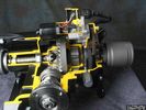
Thread upload14 viewsImage uploaded in thread 169349
|
|
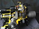
Thread upload10 viewsImage uploaded in thread 176633
|
|

LTB00179 - Technical Bulletin - Infotainment System Lock-up - Repair Procedure79 views
|
|

LTB00199 - Technical Bulletin - Battery Vent Tube Blockage - New Design Repair Procedure63 views
|
|

LTB0030239 views
|
|
191k on the clock and just about to depart for an easy life.....4 views
|
|

Thread upload2 viewsImage uploaded in thread 159579
|
|
Thread upload12 viewsImage uploaded in thread 127619
|
|
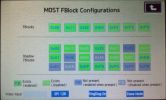
MOST FBlock106 views
|
|

26 views
|
|

Lara brand new. 2 days old with 200km on the clock.116 views
|
|
Lara with 208km on the clock114 views
|
|

Thread upload11 viewsImage uploaded in thread 190462
|
|
Thread upload10 viewsImage uploaded in new thread
|
|
Thread upload8 viewsImage uploaded in new thread
|
|

72 views
|
|
Thread upload3 viewsImage uploaded in thread 178308
|
|

Picture of old bus just prior to trading it in .... Jan 03 S model 35000 ish on clock - Had the infamous problem with liquid ingress on injector loom but after that was great car128 views
|
|
317 viewsStorage of recovery kit in 2nd battery compartment
1 x 8m strop, 1 x 2m tree strop, 2 x bow shackles & 1 x pully block
|
|

This dang guy is blocking my view of the scenic wildlife ;)516 views
|
|
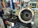
Housing and Bits1283 viewsHousing of DIII/LR3 locking differential
|
|
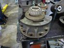
Locker and Bearing1381 viewsRusty shot bearing and locker mechanism https://www.facebook.com/DifferentialPartsUS
|
|
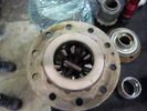
gears1217 viewsNice Gear set, most diffs only have 2
|
|
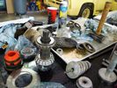
clutch in bits1257 viewssome clutch bits, pinion, etc.
|
|
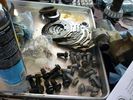
more clutch bits1188 viewsmore bits, bolts and pieces
|
|
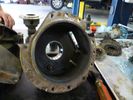
Housing and Bits1178 viewshalf of the housing
|
|
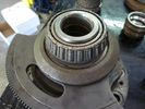
shot bearing1436 viewsshot rusty bearings https://www.facebook.com/DifferentialPartsUS
|
|

Pine Road - Road closed sign108 viewsForestry track/road (11 km north of Iluka turnoff along Pacific Highway) but blocked about 3 km along. Took Thompsons Road to rejoin highway but had to negotiate a swampy area with fallen trees across track. Road impassible without chainsaw so found a private road and headed towards Glencoe Road using a Telstra track.
|
|
Maxxraxx37 viewsMaxxraxx fixed towball mounted bike rack. Top: upright with pivot and locking pin. Bottom left: towball mount with spacer and 50mm towball. Bottom right: horizontal member with three bike carriers, securing strap and security cable.
|
|
Thread upload0 viewsImage uploaded in new thread
|
|
Locking Rear Diff29 views
|
|
Locking Rear Diff25 views
|
|
towbar in not locked83 views
|
|
Clock on summer time276 views
|
|

door lock actuator1 views
|
|

door lock actuator2 views
|
|

My Packed LR Expedition Roof Rack39 viewsShovel, 60" Hi-Lift Extreme, (2) 5 Gallon Jerry Cans in a Front Runner dual can holder, TRED 4x4 Recovery boards, and my spare 275/65/18 Goodyear MTR/Kevlar on a t-bolt mount. Almost everything is locked down except the shovel, and now the TRED's until I find a good way to mount them.
|
|

door lock actuator3 views
|
|

door lock actuator2 views
|
|

door lock actuator4 views
|
|
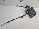
tailgate lock release cable 217 views
|
|
tailgate lock release cable23 views
|
|
Gates and yard blocking lane on back of Werneth Low75 views
|
|
i took power for camera and the reversing signal from the main loom with scotch locked365 viewstape them up otherwise they will corrode. this area gets wet and dirty
|
|
Thread upload12 viewsImage uploaded in thread 128829
|
|
Audio amplifier & DAB unit & Door lock system106 views
|
|
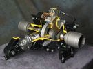
Rear Locking Diff618 views
|
|
Thread upload34 viewsImage uploaded in thread 124447
|
|

Thread upload8 viewsImage uploaded in thread 157244
|
|
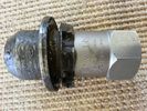
Removed Locking Wheel nut16 views
|
|
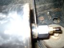
Reservoir Air In fitting installed 1660 viewsSchrader valve installed. Shop air can now be introduced into the tank to facilitate the raising of the 3 when there has just been a failure of the onboard air compressor rather than the electronics or valve block wiring etc.
Air could also be sourced from this point, however the purpose of the modification is air in, not air out as the air pressure normally runs above 200 psig, too high to be safe for routine use unless a pressure reducing regulator is added per the Mitchell Bros kit.
|
|
Thread upload14 viewsImage uploaded in thread 126053
|
|
Thread upload13 viewsImage uploaded in thread 190462
|
|

Drivers Door Powerfold wing mirror connection blocks28 views
|
|
Taming the rock fall - Bird River - West Coast Tasmania810 viewsCalendar 2008 Entry - re-opening the blocked track for other Club 4wds.
|
|
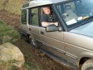
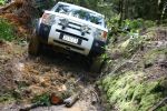
Roych Victim Number 2250 viewsA bust diff lock combined with side steps and road tyres makes for a stationary Disco 1 - took us an hour to get this over the big steps - and only then with a tow!
|
|
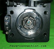
NAS 7 pin + NAS 4 pin Flat Trailer Socket308 viewsThis is the vehicle end of the NAS trailer harness that is located behind the removable plate centered within the rear bumper by the towing loop. Re the four pin flat connector, from the bottom, the exposed bare lower pin is the ground, usually the White wire on a NAS trailer. The next pin up is normally a Brown wire on a trailer and is for the Tail Lights. The third pin, normally a Yellow wire, is the left signal light; the top pin, normally a Green coloured wire, is the right signal light.
Re the round connector, from the notch in the plastic surround, clockwise, the first blade is ignition controlled +12VDC battery power, (only alive when engine running), and on the Land Rover factory harness is an Orange wire; on a NAS trailer, usually Red but perhaps a Black wire.
Next blade clockwise at 3:00 o'clock above, is the Right Turn signal light, a Green wire on the LR harness, and also on a NAS trailer.
At 5:00 o'clock, the next blade is for the Electric Brakes and is Blue on both the LR harness and on a NAS trailer.
The Ground wire is next, White on both the LR harness and on a trailer.
At 9:00 o'clock above, is the Left Turn signal, Yellow on both the LR harness and on a trailer.
The last blade to the left of the line up notch is the Tail Light circuit. On the LR harness, the wire colour is Brown with two White stripes and on a NAS trailer, Brown.
The centre pin is for the Reverse Back Up lights and is Black on the LR harness and often Purple on NAS trailer wiring but can be Black also.
Note that when the socket assembly is installed on the 3, the notch in the plastic surround is on the left - that is rotated 90 degrees anticlockwise to the picture above. In other words, When installed on the 3, the 4 pin flat connector lays horizontal and is located below the round socket.
|
|
Clock spring wiring pinout ish70 views
|
|
48 viewsYou will need to hold the fan drive in place whilst you undo the large nut in oder to remove the fan. This is a Left Hand thread, so it undoes by turning in a Clockwise direction.
|
|
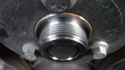
39 viewsThis is a Left Hand thread, so it undoes by turning in a Clockwise direction.
|
|
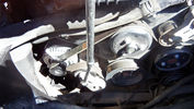
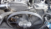
67 viewsThis is easy to remove. You will notice the tensioner at the bottom left near the alternator. There is a sqaure slot on the tensioner into which fits a 3/8" square drive. Just turn anti-clockwise and the tensioner is moved away to slacken the belt and off it comes.
|
|
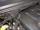
Main Feed799 viewsHere\'s the shielded positive feed from the main battery. Runs accross the fireall with lockties to support.
|
|
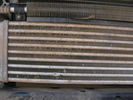
Blocked intercooler left side110 views
|
|
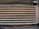
blocked intercooler right side111 views
|
|

Thread upload3 viewsImage uploaded in thread 200758
|
|
Thread upload3 viewsImage uploaded in thread 165158
|
|

Thread upload7 viewsImage uploaded in thread 187408
|
|

Thread upload5 viewsImage uploaded in thread 187408
|
|

Thread upload11 viewsImage uploaded in thread 186251
|
|

Thread upload2 viewsImage uploaded in thread 186251
|
|

Thread upload2 viewsImage uploaded in thread 186251
|
|

Thread upload2 viewsImage uploaded in thread 186251
|
|

Thread upload4 viewsImage uploaded in thread 186251
|
|

Thread upload3 viewsImage uploaded in thread 159579
|
|

Thread upload3 viewsImage uploaded in thread 159579
|
|

Thread upload3 viewsImage uploaded in thread 192616
|
|

Thread upload4 viewsImage uploaded in thread 193438
|
|

Thread upload5 viewsImage uploaded in thread 194599
|
|

Thread upload5 viewsImage uploaded in thread 194599
|
|

Thread upload1 viewsImage uploaded in thread 195939
|
|

Thread upload1 viewsImage uploaded in thread 195046
|
|

Thread upload2 viewsImage uploaded in thread 194599
|
|

Thread upload4 viewsImage uploaded in thread 186251
|
|

Thread upload3 viewsImage uploaded in thread 197664
|
|

Thread upload1 viewsImage uploaded in thread 186251
|
|

Thread upload4 viewsImage uploaded in thread 198490
|
|

Thread upload2 viewsImage uploaded in thread 186251
|
|

Thread upload7 viewsImage uploaded in thread 186251
|
|

Thread upload2 viewsImage uploaded in thread 186251
|
|

Thread upload1 viewsImage uploaded in thread 186251
|
|

Thread upload2 viewsImage uploaded in thread 186251
|
|

Thread upload4 viewsImage uploaded in thread 186251
|
|

Thread upload13 viewsImage uploaded in thread 199861
|
|

Thread upload7 viewsImage uploaded in new thread
|
|

Thread upload1 viewsImage uploaded in new thread
|
|
Thread upload18 viewsImage uploaded in thread 103657
|
|
| 442 files on 2 page(s) |
 |
1 |  |
|