| Search results - "rds" |
Main road to Isafjörður in the northwest fjords of Iceland112 views
|
|
In the northwest fjords129 views
|
|
2 birds and tit having fun in the snow43 views
|
|
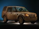
Muddy LR3 at US SUV of the Year Awards3659 views
|
|
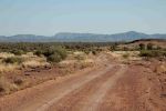
Owen Springs - Towards the West MacDonnell Ranges157 views
|
|
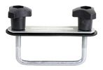
32 viewsHalfords fitting kit
|
|
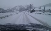
A5 towards CApel Curig44 views
|
|
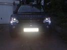
led with guards140 views
|
|
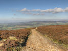
Rudland Rigg45 viewsThe view from the top of Rudland Rigg looking out towards Roseberry Topping and the coast.
|
|
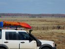
Cordillo Downs Road between Birdsville and Innamincka34 views
|
|
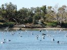
Thousands od Sea Birds Thousands of Km from Ocean - Innamincka28 views
|
|

118 viewsTraxide brain mounted. It's mounted slightly tilted towards the front of the engine bay so as to give as much space as possible to the brake vacuum pipe behind it.
|
|
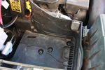
112 viewsDue to the side terminals protruding out the side and affecting the battery clamp, I found the battery will fit better if it could be pushed a few millimeters towards the engine. This lip will have to be removed.
|
|
Thread upload4 viewsImage uploaded in thread 121845
|
|
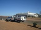
Birdsville Pub71 views
|
|

3 Point Hitch on Series 90148 viewsUsually one sees the Series units with just a conventional field plow hooked to a drawbar hitch, tractor style. This jpg however is the full meal deal - a 3 point hitch, probably off a Fordson tractor, in the long tradition of Ford/Land Rover cooperation.
|
|
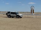
Birdsville Races85 views
|
|
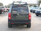
Rear ladder with expedition roof and taillight guards57 views
|
|

Rear light guards fitting instructions56 views
|
|

D3 and D4 a-arm guards (front & rear)96 views
|
|
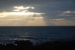
View from verandah towards Norther Ireland172 views
|
|
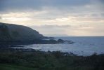
View from verandah towards Isle of Man198 views
|
|
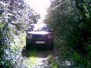
Lunchtime Lane197 viewsNot 200 yards from Manchester Airport can be found a little 1/2 mile lane - did it for the first time today - a few minutes fun in a dreary day
|
|

Thread upload6 viewsImage uploaded in thread 174456
|
|
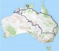
Our Trip Apr-Aug 2008132 viewsGosford to: Broken Hill, Innamincka, Birdsville, Alice Springs, Bungle Bungle NP, Broome, Gibb River Rd to Mitchell Falls and then Kunnunurra, Darwin (for tail gate Repair), Normanton (via Roper Bar, Borroloola, Lawn Hill, Burketown), Townsville, down coast to Noosa then inland to home. TRACK TRACE BY TRACKRANGER SOFTWARE ON ASUS UMPC.
|
|

Thread upload2 viewsImage uploaded in thread 202129
|
|

81 views
|
|
58 views
|
|

Thread upload38 viewsImage uploaded in thread 111190
|
|

Thread upload37 viewsImage uploaded in thread 115982
|
|
235 views
|
|

Thread upload2 viewsImage uploaded in new thread
|
|
Thread upload2 viewsImage uploaded in new thread
|
|
Thread upload1 viewsImage uploaded in new thread
|
|
bollards162 views
|
|
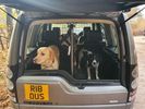
Thread upload10 viewsImage uploaded in new thread
|
|

Brake Light Switch, Find, Remove, and Install Instructions 7775 viewsThis is a two page doc outlining where to find the brake light switch, how to remove it, and then install the new one.
Note, do not move the brake pedal when removing or installing the switch. Let the brake pedal hang where it wants to. The switch design is actually cunning, and as such is supposed to make the removal and install fool proof. Hence if you think too much about it, you can wreck the new switch.
If you want to inspect the interior of the switch, wait until you have removed the old switch. You can then just unsnap the blue from the white to get it apart. Inside, the switch is quite simple, (no circuit boards), but it will probably show black dust from failing contacts.
I think the reason the switch fails is that the Normally Open, (NO), contacts of the brake light contacts were made too light to carry the current load for make and break of the tail light filaments. I also think the black dust created then fouls the Normally Closed, (NC), second set of contacts for the ABS circuit. As such, the Normally Closed contacts become intermittent in operation and display as a fluctuating open and closed circuit condition to the ABS system when the ABS should be seeing a steady closed circuit. Hopefully the replacement switch contacts are more robust and may be as I recently replaced my switch again just as a matter of maintenance. While in a redesign, ideally the NC contacts should be sealed or at least separated from the NO contacts, when I inspected the removed switch, this time there was no black dust present.
Probably the removed switch will have a Land Rover oval logo moulded into it, the new one, FOMOCO.
|
|
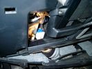
Brake Switch Visible thru Opening4933 viewsThe blue and white bit is the switch; the sort of gold appearing box,(it is really black), you will not see in your 3 as it is a Smooth Talker brand amplifier for my Blackberry phone antenna. This install is detailed in the SmoothTalker phone antenna section of my gallery.
One way to remove and install the switch is to lower the "horizontal" panel above the brake pedal as shown where the flashlight head is located. To actually remove the switch, you slide your hand thru the gap and rotate the switch clockwise 1/4 turn while watching thru the rectangular opening. Installation of the new switch is the reverse of above - 1/4 turn counterclockwise.
Before you remove the switch, note its orientation - horizontal with electrical wires to the left. That is the way it should look after replacement as well.
The second time I replaced the switch, I did it all thru the rectangular opening and did not remove the horizontal panel - that is experience helping out.
The knee kick you have to remove regardless. It is sort of hinged at the bottom so you just pull at the top and sort of rotate the knee panel and then pull upwards for two plastic "fingers" to clear the slots they reside in.
|
|
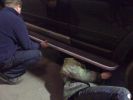
D3 Side Step Repairs168 viewsNearly finished - just the last two rivets to put in. We used a very basic and cheap hand rivet gun which can be bought in places like Halfords for about £10.00 and usually come with a supply of rivets to do the job.
|
|
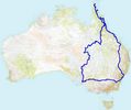
Cape York 201142 views12969km May/August 2011 - Cairns, Cape York, Longreach, Birdsville
|
|

469 viewsSide steps, light guards, rubbing strips, roof bars, privacy front and rear
|
|

Mvubu in Botswana 2014118 viewsMvubu 2014 Discovery 4 TDV6 XS, Corris Grey.Snorkel, OL Bull Bar, Winch,OME Heavy Duty Coil Springs,Light Guards,17" Black Wheels,Cooper ST max,Dual Battery+Inverter,Drawer Storage,FR Rear Ladder,Hannibal Roof Rack,80L Excel Long Range Fuel Tank,HiLift Jack Points,75L Water Tank.
|
|

COSMETIC STANDARDS DISCO237 viewsCOSMETIC STANDARDS DISCO
|
|
131 views
|
|
63 views
|
|
70 views
|
|
64 views
|
|

65 views
|
|
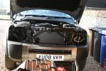
Fitting lamp guards182 views
|
|
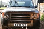
Lamp guards fitted148 views
|
|
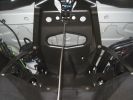
95 viewsSpare wheel well looking towards front of car.
|
|
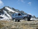
D3 High Alpine Pass450 viewsCALENDAR ENTRY
Sept.08 on the way back from Monaco towards Switzerland. The \'Col de L\'Iseran\' is the 3rd highest road in Europe and this shot is taken slightly higher than that!
|
|
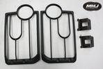
Thread upload6 viewsImage uploaded in new thread
|
|

D4 A Bar, driving lamps and lamp guards150 views
|
|
![Filename=D4 lamp guards [1600x1200].JPG
Filesize=328KB
Dimensions=1284x959
Date added=05.Feb 2011 D4 lamp guards [1600x1200].JPG](albums/userpics/13223/thumb_D4%20lamp%20guards%20%5B1600x1200%5D.JPG)
380 views
|
|

Thread upload8 viewsImage uploaded in new thread
|
|
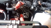
+12V supply135 views+12V taken from the regulator used to power the start/stop battery from MY14 onwards
|
|
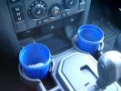
375 ml jam container369 viewsThese are the 375ml Danish Orchard brand jam containers. They fit fairly tightly into the original old style, (2005/6) Land Rover 3 factory cup holders. The extra height provided by the containers can be an advantage. I have a similar assortment of containers in some of the door panel located wine bottle holders to better hold containers of lesser valued products.
|
|

158 viewsGood for a laugh
|
|
added light guards & bashplate55 views
|
|
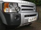
added light guards & bashplate56 views
|
|

2 more awards for D3167 viewsMedia release from LRA - Dec 2008
|
|

Thread upload10 viewsImage uploaded in new thread
|
|
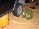
Success in the sands128 viewsAir jack almost fully inflated, suspension in extended mode on soft sand, sloping towards the camera.
|
|
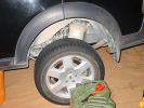
Off the ground143 viewsCar is on a desert sand sideslipe towards the camera - worst combination I could think of. Fully inflated, jack lifts the rear off by about 25mm, with suspension in extended mode.
|
|
Halfords Booster Cables33 views
|
|
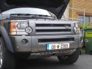
Lense Guards On97 views
|
|
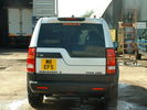
lamp guards43 views
|
|
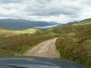
Corrieyairack pass 200632 viewsDescending towards Fort Augustas
|
|
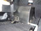
Left hand side of internal 40 Litre water tank161 viewsView from floor looking towards tank. Top white cover is 50mm plastic pipe cap. It protects the tank vent valve. Dispensing hose is at lower corner of tank
|
|
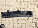
Top view of "Uncle Ray" discrete winch tray, after painting.103 viewsNote that towards the upper right there is a notch in the tray. This is needed for the specific winch's electric solenoid. The winch is a Mile Marker 12,000 lb hydraulic unit.
|
|
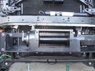
Close-up front view of partially-installed winch120 viewsNote that the sheet-metal flange just above the winch had to be notched to allow winch controller to be actuated. Also this same bracket had to be bent upwards to allow the winch hydraulic:electic solenoid to fit without rubbing. The nut on the upper-left bolt (the one with a very faint circle around it) stripped on re-installation, so the tray and winch pulling load is held only by the threads on 7 bolts....
|
|
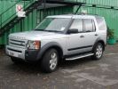
337 viewsSide steps, rubbing strips, lamp guards & roof bars.
Rear windows tinted with darkest \'limo\' tint, side windows with one shade lighter (but still slightly darker than factory option).
|
|
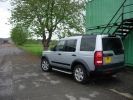
287 viewsSide steps, rubbing strips, lamp guards & roof bars.
Rear windows tinted with darkest limo tint, side windows with one shade lighter (but still slightly darker than factory option).
|
|
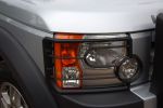
Front lamp guards, look great but offer little protection388 views
|
|

calendar entry480 viewsHigh in the Iceland Interior June 2008 - View towards the Vatnajökull Glacier range - Car is G4 Challenge Event Car from 2006 - Team Germany / Spain - Stage 3/4 Bolivia
|
|
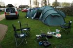
Camping inn Oxfordshire413 views
|
|
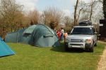
Camping inn Oxfordshire460 views
|
|
Thread upload21 viewsImage uploaded in thread 134782
|
|
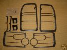
Lamp Guards219 views
|
|

9 views
|
|
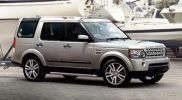
First showing of Front Lamp Guards on the Discovery 4156 views
|
|
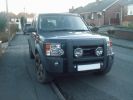
Front Lamp Guards Fitted200 viewsThe hardest part was extracting the front grill from behind the nudge bar and driving lights!
|
|

66 views
|
|

Front Light Guards Fitting66 views
|
|
Thread upload1 viewsImage uploaded in thread 114491
|
|

Front Guards10 views
|
|

FuelFilter_VIN__07MY_onwards.pdf38 views
|
|
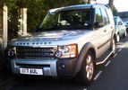
D3 Chrome Grille and Guards added199 views
|
|

Thread upload10 viewsImage uploaded in thread 136297
|
|
Thread upload3 viewsImage uploaded in thread 188579
|
|
14 views
|
|

Thread upload14 viewsImage uploaded in thread 160605
|
|

43 views
|
|

My Wife161 views
|
|

Cyc.202 viewsOne of My dogs. Cyclops. Yes he has two eyes. He is called Cyclops because He used to walk backwards, sometimes, when he was a pup & He is a monster.
|
|
Impact Skid after hitting wayward Hilux207 viewsDisco3 was stopped when a skidding Hilux collided with it. Collision caused Disco3 to slide backwards
|
|
New light guards16 views
|
|
Light guards broken clip15 views
|
|
Oops16 viewsThat's why it stopped moving forwards and started moving down!
|
|

From Nast looking to head of loch towards Poolewe1 views
|
|

Baby leopards. Mother was shot3 views
|
|
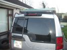
Waffell boards fixed in place558 views
|
|

Switch is blue colour thing thru the rectangular opening.3149 viewsThe blue coloured plastic bit thru the rectangular opening is the brake light switch. The fist time, I found it easier remove the switch by dropping the horizontal plastic panel, (two screws), and then slipping my hand in and rotating the switch clockwise 1/4 turn. The second time, I was able to remove the switch thru the rectangular opening and did not need to remove the horizontal lower panel. Obviously, I had to remove the sloping knee pad panel, (note sort of hinged at the bottom so pull back from the top.)
Regardless, do not touch the brake pedal - just let it sit where it wants to. One has to first remove the angled knee pad panel that sits under the steering wheel. It can be pulled from the top corner at the door side. Pulling releases a pair of those U shaped metal clips that LR loves so dearly. You have to pull quite hard. The bottom is held by a couple of plastic fingers in a couple of slots so you pull at the top till the two clips release and then rotate the panel and pull upwards a bit.
To remove the switch, you rotate it clockwise and pull outwards. Rotating the switch clockwise automatically retracts the plunger back into the switch body away from the brake pedal arm.
Similarly when you install the new switch, the required 1/4 turn anti clockwise rotation action releases the plunger so it lays up against the brake pedal arm and at the same time, secures the switch in place.
To remove the electrical wires, the switch will drop below the horizontal pad and hang from the wires so unclipping the electrical connector plug is fairly easy to do.
|
|
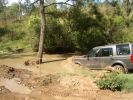
Bonatti Grey (but not mine) fords the crossing246 views
|
|

ditch it76 viewsjust another view of the ditch. i had a worry on as i came skating down the hill backwards with no means to do anything
|
|

underbody guards54 views
|
|
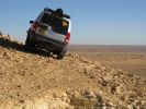
2009 Calendar Entry607 viewsView towards Jbel et-baga from, well, the edge of nowhere really!
Tunisia, Feb 2008
|
|
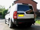
D3 sticker, chrome pipes, lamp gaurds....OMG I am going bling367 views
|
|
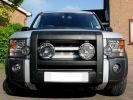
Front end - guards, A bar, spots and fogs413 views
|
|

Anybody got waffle boards?25 views
|
|
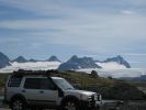
Dolafjell (1400m) looking towards Moldskredvatn Ice fields Norway August 2009237 viewsCalendar 2010
|
|
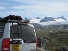
Dolafjell (1400m) looking towards Moldskredvatn Ice fields Norway August 2009248 viewsCalendar 2010
|
|
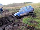
96 viewsWaffle boards not enough
|
|
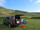
52 viewsLaugarholl campground, Strandir coast, Westfjords
|
|
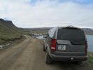
50 viewsStrandir coast, Westfjords
|
|
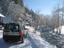
Looking towards Westendorf188 views
|
|

Looking towards Westendorf180 views
|
|
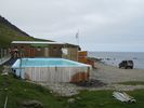
52 viewsThe swimming pool of Krossnes, Strandir coast, Westfjords
|
|
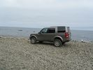
52 viewsWe are parking our car at the beach near the swimming pool of Krossnes, Strandir coast, Westfjords
|
|
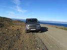
49 viewsStrandir coast, Westfjords
|
|

Guards at Garter 201128 views
|
|
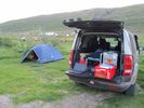
58 viewsHeydalur, Westfjords
|
|
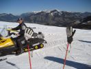
Alternative transport129 viewsView across the Brixental towards the Hohe Salve
|
|
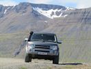
56 viewsWestfjords
|
|
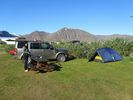
51 viewsFlateyri campground, Westfjords
|
|
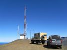
55 viewsOn the summit of Sandafell, Westfjords
|
|
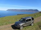
51 viewsSvalvogarvegur, Westfjords
|
|
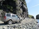
57 viewsSvalvogarvegur, Westfjords
|
|
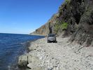
54 viewsSvalvogarvegur, Westfjords
|
|
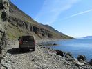
52 viewsSvalvogarvegur, Westfjords
|
|
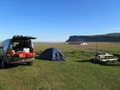
50 viewsBreidavik, Westfjords
|
|
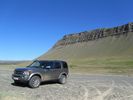
48 viewsWestfjords
|
|
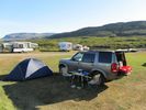
49 viewsFlokalundur campground, Westfjords
|
|
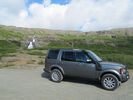
48 viewsWestfjords
|
|

Front with Winch, A-Bar, Front LIght Guards and Driving Lamps57 views
|
|
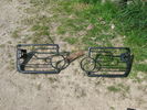
light guards30 views
|
|
Small scratch on off side rear door towards the top42 views
|
|
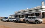
Birdsville Hotel49 views
|
|
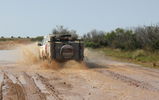
Birdsville Track36 views
|
|
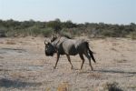
Wildebeest (Gnu) Etosha179 viewsYou generally see these together with Zebra in large herds, they are complimentary grazers
|
|

121 viewsThe tom tom did say "in 350 yards turn left" ????
|
|
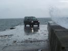
Stormy day in Islay504 viewsCALANDER ENTRY - Summer (?) holiday on Isle of Islay, Scotland. Good weather generally, but a storm came through mid-week. Car is parked at the end of the pier at Port Charlotte, looking towards Bowmore (!).
Sorry not much of a background or good light - but it was a storm. Oh and this is the highest res image I have, 5mp.
|
|
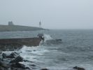
CALENDAR ENTRY - Islay 2008504 viewsSame as description for previous photo, with a bit more of a background. Looking towards Port Charlotte lighthouse. Sorry, number plate not visible, so probably inadmissible.
|
|

Thread upload3 viewsImage uploaded in thread 197816
|
|

Thread upload4 viewsImage uploaded in thread 197816
|
|

Thread upload4 viewsImage uploaded in thread 197816
|
|
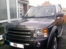
Me new Light guards 113 views
|
|
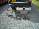
108 views
|
|
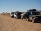
On the Birdsville Track135 viewsStoped for a dingoes breakfast, a quick pee and a look around,also just checking whats under the bonnit of the D3,dont know so just shut it.
|
|

Missing Lampguard Fixings77 viewsI\'m missing these bits from my used lamp guards!
|
|
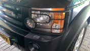
7 viewsLampguards front installed
|
|

Thread upload1 viewsImage uploaded in new thread
|
|
Thread upload32 viewsImage uploaded in new thread
|
|
100 views
|
|
Thread upload0 viewsImage uploaded in thread 206840
|
|
14 views
|
|
143 views
|
|

Rear light guards58 views
|
|

Clear Plastic Light Guards with film52 views
|
|
Thread upload10 viewsImage uploaded in new thread
|
|
Thread upload12 viewsImage uploaded in new thread
|
|
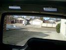
Boot lighting, looking to rear - hatch closed 539 viewsView shows the lights mounted in the rear on an early spring day.
In operation, the lights are tilted so that they shine downwards. The lights are mounted high enough up that one cannot see the LEDs from the front thru the rear view mirror; also the LEDs are so directional, that no light is thrown on the side glass.
Each assembly contains 15 LEDs, however the reflector is such that the LEDs appear to double.
|
|
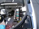
View from front left side looking towards rear aux battery compartment under cover 643 viewsAs there is no Fuel Burning Heater in the NAS V8 petrol vehicles, there is space available to install the FASKIT panel here. The piping is such that each air spring can be isolated from the air system and then filled one at a time manually via the Schrader valve. There are five Schrader valves and five shutoff valves. The fifth valve nearest the gauge controls air from the compressor, and can provide fill up air via a jumper fill line assuming the compressor is still operational.
|
|

Rear lamp guard fitting instructions402 views
|
|
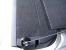
Flexible wire rope fishing leader 0.032" diameter exiting carpet 1931 viewsThis is all you see of the completed mod.
The short little angled "line" about an inch long that looks like a piece of debris and is located a few inches "above" the support cable is actually the wire rope release cable exiting from under the carpeted lift gate cover.
I drilled a very small hole in the carpet and pushed the 0.032" diameter release wire thru and then slipped the loose end under the black plastic.
To release with the lift gate etc closed, from the inside, just pull the loose end free from under the black plastic and gently pull wire about 5mm, (1/4"), and the upper door catch should release. You will have to manually push the upper door out wards to actually effect opening, but you will already be inside the rear cargo area so that part is easy to do.
The assumption is that the lower door latch still works electrically and hence, the lower lift gate half will open as normal by pressing the usual button on the top left of the lower door half.
|
|
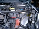
Wiring (tubing) loom at left headlight showing FASKIT panel 582 viewsThis shows the wiring (tubing) loom and FASKIT panel mounted to left wing. The loom moves a a couple of inches (50mm) towards the bottle once the headlight is put back in as there is not enough free space for the loom as located. The FASKIT panel is just visible at the top left corner of the picture.
|
|

lr3-kaymar-closed with 20"402 viewsthe kaymar carrier, designed to allow two tires, sets them both a bit outboard, thus blocking the lamp. that\'s when I realized why they put the fully functional lamps in the bumper (functions: running, brakes, signals, hazard)
I plan to re-weld the locating section more towards the middle of the rear similar to Disco II orrientation.
|
|

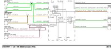
Stop Light Lamp Circuit pdf2461 viewsThis pdf shows the brake light circuit for the NAS LR3.
Note that power for the brake light bulbs can come either thru the brake light switch power feed /contacts plus also from the Hill Decent Control, (HDC), system relay located within the Central Junction Box, (CJB) - yes two separate sources of power for the brake light bulbs. This would tend to explain how a brake light circuit concern shows up as a hill decent fault message; also why lesser vehicles without hill decent braking mechanisms, (HDC), never display this sort problem when a brake light bulb or switch acts up. You never have a problem related to a system that does not exist.
Additional evidence of the relationship of the HDC and the tail light circuit is demonstrated by when the HDC actually acts to slow the 3 down, the brake lights automatically illuminate even if the slowing action was merely retarding the engine speed or shifting to a lower gear, (in other words, no foot on the brake pedal).
There is also a tie in to the Cruise Control and hence a failing brake light switch can affect cruise operation or just create false Cruise Control messages. To further complicate the issue, while there are no messages generated, operation of the radiator electro viscous fan can also be negatively affected by the fouled set of secondary contacts within the brake light switch. This is all because the NC contacts within the brake switch send misleading messages to the ECU.
While the ground wire design is similar to other vehicles, note the grounds for the brake light filament and the reverse light filament are common on each side. That means that if one has a non functioning brake light on one side, the reverse light may not also work or that some problem with the reverse lights could back feed into the brake lights. This situation while unusual, can result when grounds are corroded probably due to swimming in rivers and creeks or just routine driving in a marine environment.
|
|

Thread upload30 viewsImage uploaded in thread 118475
|
|
Thread upload41 viewsImage uploaded in thread 173514
|
|

Thread upload42 viewsImage uploaded in thread 173514
|
|
lifeguards on duty16 views
|
|
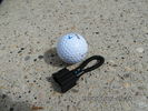
MOST fiber optic loop tool466 viewsThe looping tool in the jpg uses the Land Rover type plastic fiber optic cable with both ends feeding back into a female fiber optic connector that mates with the male fiber optic connectors on the Land Rover system.
The purpose of the loop is to allow one to disconnect MOST connected items such the BlueTooth module or the HK amplifier but allow the MOST system to still transmit signal from the head unit as the circuit would remain closed and hence complete. Of course with the Bluetooth module disconnected, there would be no Bluetooth available, however the radio and NAV would still function.
The looping tool allows one to troubleshoot the system by removing one component at at time from the MOST loop. In other words, what might appear to be a radio problem could be a Bluetooth problem - that sort of thing.
|
|
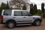
My new Disco, LR side steps,lamp guards & wind deflectors443 views
|
|

Thread upload2 viewsImage uploaded in thread 126682
|
|
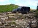
D4 HSE Green Lane on the Steps above Hawes264 views
|
|
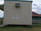
Parking Near Saleyards at Warwick154 viewsPrompted by the photo of generous parking at Walmart (USA), see how we do it in Australia. Trick, your vehicle must be narrower than about 100mm or a 2 dimensional facsimile only.
|
|
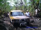
179 viewsPart of the trail the D2s trainsmission started working in reverse so he drove the trails backwards until he got stuck here!
|
|

29 views
|
|
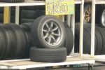
Secondhand Minilites?202 viewsI wish that these were available for the Discovery 3 in 8x17 or 18" sizes.
Lots of secondhand tyres and rims stacked around tyre and motor car dealers yards everywhere we went in Japan from Hokkaido right down to Kyushu.
|
|
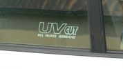
Translation Madness194 viewsAs usual in Japan, they have a love of English words and you see some funny things on T shirts, etc. but this took the cake on a little Honda Logo. Yes, it was equipped with glass windows and UV tint film.
|
|
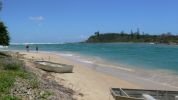
Sandon - Northern side of Sandon River looking towards Sandon Bluff from camp grounds south of Broom's Head92 views
|
|
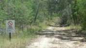
Pine Road - Road closed sign107 viewsForestry track/road (11 km north of Iluka turnoff along Pacific Highway) but blocked about 3 km along. Took Thompsons Road to rejoin highway but had to negotiate a swampy area with fallen trees across track. Road impassible without chainsaw so found a private road and headed towards Glencoe Road using a Telstra track.
|
|
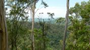
Minyon Grass - view towards south105 views
|
|
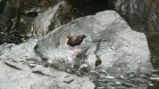
Unknown bird at sand pumping station near mouth of the Tweed River122 viewsNoisy little bugger who remained under walkway but eventually came out and then flew away flying low over water towards Tweed Heads.
|
|
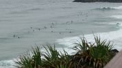
Point Danger - Looking towards Duranbah and NSW142 viewsNot a great swell but definately the most board riders I have seen there for a while. A dangerous beach, but great for board riders, adjacent to the Tweed River entrance.
|
|
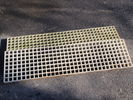
Heavy Duty Waffle Boards25 views
|
|
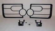
Lamp Guards2 views
|
|
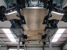
D3 and D4 Underbody Protection177 viewsIncludes:
Sump guard
Centre guard (transfer box, exhaust, fuel tank)
Rear diff guard
A-arm guards
|
|
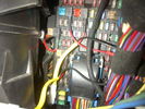
Fuse Panel showing F35P Add A Circuit installed1230 viewsFive amp fuse F35P is located towards the top left in this jpg. The other three Add A Circuit devices are for other items - powering my cell phone base etc.
Note the orientation of the Add A Circuit as this matters. Also one can just see a red tab sticking out from behind the device. The red is the conductor crimp end of a narrow 2.8mm male spade type connector that inserts into one of the "fuse" slots.
|
|
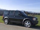
Looking towards the Kampenwand313 views
|
|

My Packed LR Expedition Roof Rack38 viewsShovel, 60" Hi-Lift Extreme, (2) 5 Gallon Jerry Cans in a Front Runner dual can holder, TRED 4x4 Recovery boards, and my spare 275/65/18 Goodyear MTR/Kevlar on a t-bolt mount. Almost everything is locked down except the shovel, and now the TRED's until I find a good way to mount them.
|
|

LR Expedition Roof Rack with TRED recovery boards.37 views
|
|
Essex Fords Feb 08112 views
|
|
Essex Fords Feb 0896 views
|
|
Essex Fords Feb 0896 views
|
|
D3\'s leaving shit-central heading towards Molares85 views
|
|
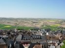
111 viewsView over the village towards vines from the tower.
|
|
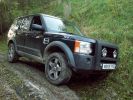
My D3 waiting whilst we towed the dead RR classic backwards!261 views
|
|
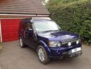
D4 with ProSpeed Rack, RAI, Winch, Auxillary Hella HIDs and Lamp Guards347 views
|
|

15 views
|
|
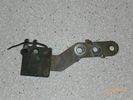
Radio Noise Suppression Capacitor NNW502820695 viewsThis is the radio noise suppression capacitor, part number LR020488 (previous NNW502820), that is mounted underneath and near the transmission. It is powered by fuse 10 amp F30E in the engine compartment. If F30E blows, (the fuse that also powers the transmission ECU), the problem is probably caused by the failed capacitor, not the ECU. A quick fix is just to disconnect the capacitor and replace the fuse as nothing bad seems to immediately result.
The above radio noise capacitor is not to be confused with LR004160, the ignition noise capacitor which is located under the black plastic engine cover on the right hand side above the air intake towards the rear of the engine.
The ignition capacitor is held on with a single 8mm bolt and a three wire electrical connector. Replacing the ignition capacitor as a routine maintenance prevention action at 100,000 miles, 160,000 km), has merit. It is a do it yourself kind of thing and easier to get at than the radio capacitor underneath.
|
|
169 views
|
|
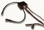
RDS Digital Thermometer240 viewsRDS Digital Thermometer
|
|
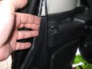
pull outwards here342 views
|
|

Rear Lamp Guards Three Quarter View102 views
|
|

Serious paint marks from rear lamp guards78 views
|
|
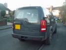
Rear Lamp Guards Fitted148 viewsSlightly trickier than the front one
|
|

56 views
|
|
Thread upload3 viewsImage uploaded in thread 114491
|
|

Rear Guards39 views
|
|

Rear Guards29 views
|
|

Rear Guards8 views
|
|

Rear Lamp Guards Fitting Instructions27 views
|
|

Thread upload3 viewsImage uploaded in thread 200203
|
|

25 views
|
|
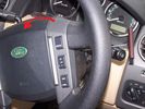
18 viewsThe Airbag will release and can be pulled towards you gently.
|
|

Replacing the blower motor572 viewsThis is a 6 page pdf with regards to replacing the HVAC blower fan and the associated fan speed module in a LHD North America spec LR3. The fan can be replaced from below and it is not necessary to pull the dash apart.
|
|
Thread upload19 viewsImage uploaded in thread 99834
|
|
Thread upload22 viewsImage uploaded in thread 99834
|
|
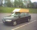
DIY roofbox237 viewsNo, it\'s not a bookcase on a vectra - it\'s a home-made roofbox. Eat that, Halfords!
|
|

Rosen A10 Manufacturer Installation Manual759 viewsThis is a 30 page pdf from Rosen that explains how to install the A10 unit. It is Generic in nature and hence carries detail not found in the LR specific install instructions. It also uses words and pictures instead of just pictures, hence can be a bit easier to figure out, particularily if you wish to take advantages of some of the hidden features not described in the LR material.
One of these features is how to hook up to a headrest display or I suppose even to the NAV in front.
|
|
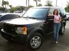
Right after I purchased my new baby...I\'m looking a little flushed afterwards.755 views
|
|
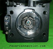
NAS 7 pin + NAS 4 pin Flat Trailer Socket304 viewsThis is the vehicle end of the NAS trailer harness that is located behind the removable plate centered within the rear bumper by the towing loop. Re the four pin flat connector, from the bottom, the exposed bare lower pin is the ground, usually the White wire on a NAS trailer. The next pin up is normally a Brown wire on a trailer and is for the Tail Lights. The third pin, normally a Yellow wire, is the left signal light; the top pin, normally a Green coloured wire, is the right signal light.
Re the round connector, from the notch in the plastic surround, clockwise, the first blade is ignition controlled +12VDC battery power, (only alive when engine running), and on the Land Rover factory harness is an Orange wire; on a NAS trailer, usually Red but perhaps a Black wire.
Next blade clockwise at 3:00 o'clock above, is the Right Turn signal light, a Green wire on the LR harness, and also on a NAS trailer.
At 5:00 o'clock, the next blade is for the Electric Brakes and is Blue on both the LR harness and on a NAS trailer.
The Ground wire is next, White on both the LR harness and on a trailer.
At 9:00 o'clock above, is the Left Turn signal, Yellow on both the LR harness and on a trailer.
The last blade to the left of the line up notch is the Tail Light circuit. On the LR harness, the wire colour is Brown with two White stripes and on a NAS trailer, Brown.
The centre pin is for the Reverse Back Up lights and is Black on the LR harness and often Purple on NAS trailer wiring but can be Black also.
Note that when the socket assembly is installed on the 3, the notch in the plastic surround is on the left - that is rotated 90 degrees anticlockwise to the picture above. In other words, When installed on the 3, the 4 pin flat connector lays horizontal and is located below the round socket.
|
|

Running Boards with Sills4 views
|
|
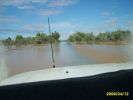
Easter 2009 - g25 viewsDiamantina Development Road just SE of Windorah towards Quilpie
|
|
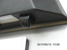
Tailgate Camera located above license plate.594 viewsThis aftermarket camera is mounted on my 2005 LR3 in almost the same location as the factory cameras. The factory units are mounted somewhat more forward closer to the metal of the tail gate and I could have done the same as well.
Note that the camera above is aimed a bit towards the centreline of the vehicle per the factory install.
|
|

Thread upload5 viewsImage uploaded in new thread
|
|
Thread upload0 viewsImage uploaded in thread 192904
|
|
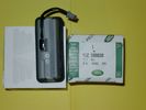
Upper Hatch Release Switch LR Part Number YUZ500020672 viewsThis is the Range Rover Sport switch, Land Rover part number YUZ500020, as it comes out of the box. Note the JAE, (Japanese Aviation Electronics), male wiring connector installed on the end of the power lead.
The rubber cover of the switch is sealed to the plastic body of the switch whereas in the previous switch design, there was no sealing. Also the replaced switch was hard wired into the same harness as the license plate lights - no JAE connector in other words.
|
|
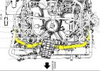
TDV6 Birds eye view of engine256 views
|
|

The Disco 3 the day I bought it71 viewsSince then here's what's been done
1) New slotted and dimpled EBC rotors and Pads
2) Rover Specialties rock sliders
3) Clear color side markers
4) Front & Rear LR lamp guards
5) Rebuilt both of my Non working Key FOBS by replacing batteries. - I can't believe I didn't even check these when I bought the vehicle.
6) Changed the LR3 emblem to Discovery 3
7) Terrafirma Front Skid Plate
8) Tactical 4x4 Gas Tank Guard
9) ASFIR Rear Diff Guard
10) Here are the things now mounted on Roof Rack
- Full size 18" MTR/Kevlar
- (2) 5 Gallon Jerry Cans mounted in Front Runner holder
- 60" Hi-Lift X-treme Jack
- Shovel
- Magnetic CB Antennae
|
|

57 views
|
|
199 views
|
|

Interior16 views
|
|
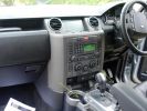
Dash trim removal577 viewsClips are at the bottom only, so pull (very hard) at the bottom and pull towards the gear lever.
|
|

I\'m Awake - you barstuards!!!103 views
|
|

Vehicle Maintenance Log for LR3/4 D3/4 or other1127 viewsThis is a Excel file that you can download and then modify to suit. It is very simple, but allows me to keep track of most maintenance and fixes etc on my LR3. All columns and rows and boxes can be edited.
I did not erase any data in the various boxes so you could see how I am using it - again not very fancy but it works for me. Under the brakes column, one will see f6 r5 which is how I keep track of the condition of the brake pads. The dealer records the pad thickness at each oil change so that is where the numbers come from.
f is for Front Pads, 6 is for 6mm; r is for Rear pads, 5 is for 5 mm. New pads are about 10 mm; replacement is at 3 mm or less. The amber coloured brake wear dash warning light should come on at about 2 mm.
|
|
133 views
|
|
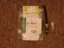
Voss System 203 connector 6 mm for valve blocks 900 viewsThis is Land Rover part number RQC000030, the Voss fitting for the axle valve blocks. I think it is a Voss System 203 6mm fitting, Voss part number 5 2 03 11 01 00.
The parts bag comes with the white plug inserted in the brass threaded bit with what is called the brass cutting ring placed on the tip of the white plastic plug. The idea is that one screws, (M10 x 1 thread), the brass insert into the appropriate hole with the white plug still in the brass insert. Once the brass is tight, (12 mm wrench), then the white plug is pulled from the assembly leaving the cutting ring down inside and under. One then pushes in the 6 mm tube end about 20 mm or so and the tube slides down thru the brass cutting ring, (2 internal sloped one way cutting ridges). When the tube is in far enough, one pulls upwards a bit and the ring cuts into the plastic such that the tube will not pull out. To remove tube, one unscrews the brass nut and all comes out, sort of like I have shown with the short piece of 6mm tubing. The white plug is a throwaway item upon install of the tubing.
|
|

D4 Rear Lamp Guards Fitting Instructions39 views
|
|

7 views
|
|

6 views
|
|
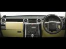
VUB504360 Grey birds eye maple facia kit399 views
|
|
32 views
|
|
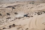
Flat out!77 viewsThis ascent was really soft and required full out power of the V8 to get up. At one stage the car was sliding sideways towards the camera nose directly up the slope with 4 sizeable rooster tails of flying sand. Not what the books tell you, but momentum has to be gained and maintained from the bottom all the way up.
|
|
Thread upload9 viewsImage uploaded in new thread
|
|
Mantec Window guards on G4RR98 views
|
|

Thread upload17 viewsImage uploaded in thread 138124
|
|

Troubleshooting pdf re Mechatronic unit on 6HP26 ZF Automatic 2129 viewsThis 21 page pdf shows possible problems within the Mechatronic unit of the ZF 6HP26 six speed automatic. On page 19/21 is a drawing showing how all the various control circuits interface with the vehicle.
Of particular interest were comments with regards to fine metal contamination of various electrical contacts. This is probably why a mere oil change can improve the operation of the transmission - reduced conductivity of the oil.
|
|

View towards Belvoir Castle from Hickling Pastures41 views
|
|
|
|