| Search results - "showing" |

0000 LR Bluetooth dealer Kit install instructions1608 viewsThis 17 page pdf is mostly a series of pictures showing how to install the original Land Rover dealer installed Bluetooth kit for circa 2005 / 2006 three's. Also included are three wiring diagrams sheets related to the pairing code 0000 Bluetooth install.
This pdf is useful if you are now removing the 0000 kit to install the optical 2121 MOST D4 module, an easier install than the 0000 kit ever was.
|
|
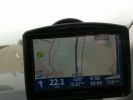
How fast?231 viewsI was driving along the Autobahn, glanced down at the speedo which was showing 140 mph, the Tomtom was telling the truth at 132 mph, but by the time I had switched the phone to camera I had dropped 2 mph, didnt try and do it again as there was no need.
|
|
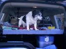
168 viewsthis is Albert 15 years old, showing the virtues of travelling club class, in the rear of a disco 3
|
|
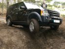
249 viewsMy baby showing off it´s air suspension :)
|
|

Photo showing bend required in hook105 views
|
|
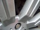
whole wheel33 viewsShowing cracks on the other 3 wheels which didnt quite fail
|
|
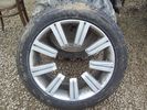
Front View35 viewsShowing the wheel which failed whilst driving.
|
|
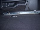
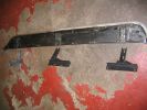
Side runner in position showing front lower than rear.33 views45%
|
|
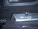
Close up of side runner, showing load hooks countersunk into runner .24 views50%
|
|
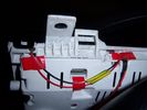
Insrument panel rear 34 viewsShowing wiring for heater and lights on indicator
|
|
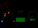
Insrument panel 36 viewsShowing heater and lights on indicator
|
|
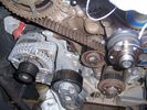
252 viewsThe old belt with rubber crumbs showing
|
|
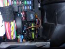
Permanent 12V supply271 viewsPhoto taken of TFC\'s D3 showing where you can take a permanent +12V supply, from the main fuse board behind the glove box.
|
|
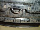
Rivetted in bracket, showing tabs that will be sandwiched by the plate95 views
|
|
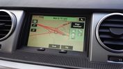
Proof of updated map data23 viewsPostal code CH4 0FB
Showing roundabouts where on current LR DVD are none.
|
|
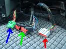
28 Dash Loom49 views
|
|
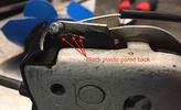
Close-up of lock showing emergency cable and pared back plastic tab141 views
|
|
5mm Allen key showing the gap - can lift vertically to go flush111 views
|
|

Matzker photo showing their car using 25mm wheel spacers. Thus the outboard look of tires.406 views
|
|
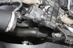
Air Box Removed1058 viewsView showing air box removed from front of EGR butterfly valve housing
|
|
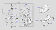
Thread upload413 viewsImage uploaded in thread 113599
|
|
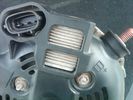
Alternator Plug and B+ terminal918 viewsPictured is the rear of the older Land Rover part # YLE500190 alternator showing the shiny cooling fin of the Regitar VRH2005-142 regulator under.
The first pin in the far left side of the connector is numbered #1 in the LR electrical wiring diagrams and is Battery Voltage Sensing (BVS); the middle pin, #2 receives a Pulse Width Modulated (PWM) signal from the Engine Control Module (ECM), and the right pin, #3 carries a PWM signal back to the ECM. Terminal Pin #2 on the LR wiring diagrams is called Alternator Control or ALT CON; Pin #3 per LR is called Alternator Monitoring or ALT MON.
Pin #1 is similar to what in older designs used to be called A or Batt, but is now called by Denso, S, AS, or Alternator Sensing for this design. Pin #1 also provides power to excite the alternator at startup until the PWM instructions over ride the battery voltage info. Land Rover calls the electronics under the pins a Smart Regulator, ironic, as it has to follow orders from the ECM rather than give the orders - new age thinking I guess. This is different from older design internal regulators that look at just the battery or the electrical buss voltage and then decides itself what to do.
It is almost like we are back to the external regulator designs of old, except that the ECM may decide that instead of telling the alternator to make more power, to load shed, and hence shut down the heated windscreen, seats, or whatever other electrical loads it decides are appropriate. My view is that the "smarts" are in the ECM and that the "regulator" should be regarded if not dumb, then as being a slave to the ECM.
|
|
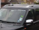
Roof rails96 views
|
|
Thread upload1 viewsImage uploaded in new thread
|
|
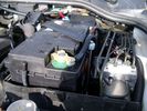
Aux Battery showing ground cable bolt "upside" down 1577 viewsIn order to obtain sufficient height clearance to get the plastic cover back on, I had to install the ground cable to the underside of the battery post connector.
Note the battery vent hose, (approx 5 ft required) is run down into where the windshield washer fluid container is located. There is not much electrical or metal in that area to be corroded by battery gas plus the open end of the vent hose tends to be protected from dirt and stays clean as well.
|
|
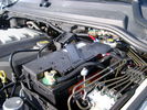
BCI Group 40R Deka 640RMF battery showing vent hose run forward to windshield washer reservoir area 1430 viewsRecessed post "Euro profile" battery to "match" OEM and stock Land Rover bracket; note that the Traxide SC80-LR module is mounted at an angle to allow for the main cable to sit under the cover so cover still closes.
The battery is a nominal 7", (180mm), high, but sits on a 1" battery spacer set under to raise the bottom front end of the battery such that the approx 11", (290 mm), length of the BCI 40R battery rises above the angled plastic nibs at the forward end bottom of the case front; hence sufficient space, (1/4", 5mm) remains at the brake reservoir end.
Also the 40R battery does not have hold down "flanges" on each end; on the sides yes, but not the ends so no additional length is required.
When I had to replace the 40R, this time I installed the shorter, (9.625"), taller, (7.5") Interstate BCI 47 / DIN H5 battery which eliminated the spacer on the bottom and better fit the stock LR tie down bolt lengths. Deka also has a BCI 47 / DIN H5 that would work fine as well.
|
|

Frame Jacking Points showing where holes are located.1088 viewsThe four points marked with the arrows show where the holes in the underside of the frame are located such than one could insert a trolley jack pin type lifting adapter, (or as designed), the official LR scissors jack.
|
|

showing off82 views
|
|

Bin Cover removed showing forward release clips that clip into the two rectangular slots.10 viewsOne has to pull up on the Bin Cover to unlatch the two metal clips, hence why release of the C pillar cover makes the bin cover removal and reinstall easier.
|
|

Buzzer located under black plastic cover.12 viewsThe white electrical connector clicks into the buzzer housing that is shown protruding from under the black plastic cover. There is a little tab on the white plastic that has to be squeezed to release the connector. In other words, do not pull on the two conductors.
|
|
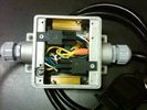
Box open showing Hella Relays and Putco Load Resistors749 viewsInterior of the box - note the two gold coloured 6 ohm 50 watt load resistors are a bit distant from the other items so as to provide some separation for dissipation of the heat generated.
Rather than a moulded plastic weather resistant box which I would have preferred, I used a bulky and much heavier metal weather tight style electrical box so the metal can act as a heat sink.
|
|

Black Deposits to interior of Brake Light Switch2860 viewsThere are two contacts, one on each side of the vertical plunger under the copper metal. The set of normally open contacts on the left side that carries the power for the brake light filaments, (15 amp fuse F15P), is apparently not heavy enough as the contacts deteriorate and generate the black residue.
The set of normally closed contacts on the other side appear to be sized OK. There is not as much current, (5 amp fuse F66P), flowing thru the contacts to the ABS module, however the contacts are likely adversely affected by the black residue produced by the other deteriorating set of contacts.
One presumes/hopes that the newer replacement switch now has contacts heavy enough to carry the brake light power. It would be ideal if the ABS set of contacts were sealed from the brake light contacts to prevent contamination of the normally closed set of contacts.
|
|
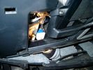
Brake Switch Visible thru Opening4973 viewsThe blue and white bit is the switch; the sort of gold appearing box,(it is really black), you will not see in your 3 as it is a Smooth Talker brand amplifier for my Blackberry phone antenna. This install is detailed in the SmoothTalker phone antenna section of my gallery.
One way to remove and install the switch is to lower the "horizontal" panel above the brake pedal as shown where the flashlight head is located. To actually remove the switch, you slide your hand thru the gap and rotate the switch clockwise 1/4 turn while watching thru the rectangular opening. Installation of the new switch is the reverse of above - 1/4 turn counterclockwise.
Before you remove the switch, note its orientation - horizontal with electrical wires to the left. That is the way it should look after replacement as well.
The second time I replaced the switch, I did it all thru the rectangular opening and did not remove the horizontal panel - that is experience helping out.
The knee kick you have to remove regardless. It is sort of hinged at the bottom so you just pull at the top and sort of rotate the knee panel and then pull upwards for two plastic "fingers" to clear the slots they reside in.
|
|
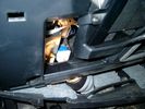
Smooth Talker Amplifier Box mounted below near steering column.179 viewsThe gold look box due to the lighting, (actually black), is the antenna amplifier located near the steering column. It can be put anyway but this seemed an OK location as I ran the antenna connector cable rearward from here to the back corner of the 3 and then up to the underside of the roof glass at the rear. The blue/white thing is the brake light switch that often must be replaced. See the Brake Light Switch file within this Gallery regarding the switch replacement.
|
|

Black Deposits on Brake Light Switch Plunger2757 viewsThis jpg I got off another forum and is typical of what one will see when one opens up the removed brake light switch. The black powder is residue from arcing of one of the pair of contacts within.
Hopefully the newer switches with the FOMOCO logo moulded into the plastic are improved from the Land Rover logo marked early units, however I doubt it.
The Ford part number is SW-6572 and/or 7E5Z-13480-A as used on the 2006 to 2009 Ford Fusion's and Mercury Milan's; the Land Rover part number is XKB500110. Cost of switch could be about twenty five dollars. A previous LR part number for the switch was XKB500030, so hopefully the newer LR part number, XKB500110, reflects some improvement in reliability.
It is possible that the new switches are better as I installed a replacement 72,000 km, (45,000 miles) later, at 195,000 km (121,000 miles). When I took the removed switch apart to inspect, it was clean inside. There was no black dust - the switch looked like new, hence they must be improved now.
|
|
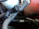
Breather line with factory cap cut off.2319 viewsIf you expand the jpg by clicking on it, in the bottom right corner if you look closely, one can see the black plastic factory vent tubing with the OEM cap cut off.
Note the tubing is cut at a 45 degree angle facing to the rear. Also shown in the top right is the cut off portion sitting on the coolant water hose and on the top left also sitting on the coolant hose, the new to be installed Gore manufactured replacement breather cap.
|
|

The Disco3 Squad, Saturday Morning216 viewsA stitch together of two photos showing all sixteen vehicles read for the off out and about in the Peak District on 1st July
|
|
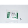
Clip Spring Metal FYC 500040 that holds LR together1747 viewsThe jpg is of the spring metal clip, Land Rover part number FYC 500040 that holds most of our 3 together - well at least most the interior trim parts.
If you are going to remove interior panels, you may as well stock up on a few for replacement as upon panel removal, the clips tend to spring away into deep never to be found voids within your 3.
|
|

Detroit Fluid DOT air line fittings718 viewsThe picture shows the internal ferrule that is characteristic of the DOT / TUV accepted fittings for highway vehicles. Most often these fittings are metal however the Land Rover John Guest 6mm straight connector is all plastic and has the internal ferrule.
|
|
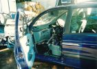
Near side showing interior226 views
|
|

C pillar cover removed to facilitate removal of bin cover.9 viewsNote the "ribbon" behind the top left corner of the C pillar cover. This is something to do with the curtain air bags, hence do not mess with it. I dislodged the cover to make it easier to pull up and extract the black plastic bin moulding. It is not necessary to totally remove it and would be what I call a big deal - seat belt, air vent and ducting as well as that curtain concern.
|
|
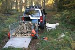
D3 at work, also showing my helper bringing me logs to cut420 views
|
|

Hog Rings and Hog Ring Pliers47 viewsHog Rings and Hog Ring Pliers showing an open and closed hog ring with 20p for scale
|
|
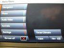
Main Navigation Menu showing 4x4 info and timed Climate173 views
|
|
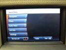
Main Navigation Menu showing 4x4 info 143 views
|
|
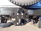
Defender 19 viewsDefender showing trailair camera fitment
|
|
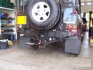
Defender22 viewsDefender with adjustable tow bar showing trailair camera fitment
|
|

Thread upload17 viewsImage uploaded in thread 170233
|
|

Thread upload21 viewsImage uploaded in thread 170233
|
|

Video showing TR working to counter wheelspin573 viewsTaken at off road day in Henley In Adren Warwickshire, a good fun day out.
|
|
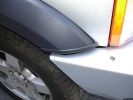
ARB Bull bar - closeup of drivers side showing trim finish.244 views
|
|
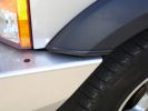
ARB Bull Bar - closeup showing trim finish of Wheel trim.224 views
|
|
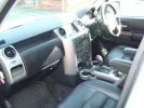
For Showing52 views
|
|

Rear ladder showing black & silver LR logo216 views
|
|

Paulo showing a Himba warrior his own photograph148 views
|
|

IBS contoller showing battery condition (engine off)217 views
|
|
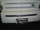
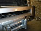
Showing neat winch set up. Front cover removed251 views
|
|
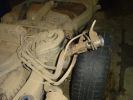
85 viewsFuel filler, showing rear diff breather pipe
|
|
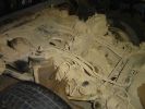
103 viewsRear shot, showing diff and fuel tank breather pipes running up to filler neck at top LHS
|
|
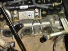
Dead engine135 viewsExhaust ports showing where leaked coolant has gone into the manifold and filled the turbo
|
|
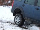
Showing Extent of \'extended mode\'392 views
|
|

Another view50 viewsA view of the general area showing the damaged part, lower centre. The second occurrence shows similar damage.
|
|

2nd Row footwell, showing water dispensing hose144 views
|
|
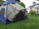
Tent showing vehicle 'sock'167 views
|
|

Photo showing inside sock.166 viewsThere is a double layer inside. Just like a conventional tent, the waterproof layer, then a flysheet. Both can be zipped/unzipped when vehicle is not in place.
|
|
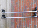
Showing manufacturers designed profile in bars.21 views
|
|
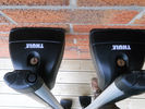
Showing Thule locks21 views
|
|
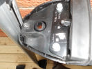
Showing T-trax feet adaptor.24 views
|
|
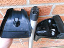
Security cover off showing lock.22 views
|
|
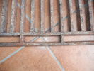
Base showing tiny crack31 views
|
|
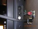
maxxraxx fitting - showing electrics now accessible!400 views
|
|
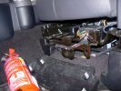
Mounting a non-LR fire extinguisher535 viewsShowing the plastic cover removed. I will make up a metal plate or bar so that the extinguisher frame can be mounted directly to this framework under the seat.
|
|
Roof Bars closer84 viewsRoof bars for sale, showing small cut/nick
|
|
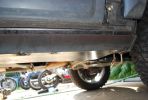
194 viewsRight front showing rough fit of the slider
|
|
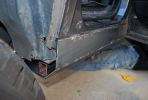
183 viewsRough fit showing the rear end with the support channel and slider plates.
|
|
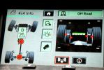
4x4 info screen showing both diffs hard at work145 views
|
|

D pillar speaker cover removed to facilitate removal of the bin cover.11 viewsThe pipe thing exposed when the D pillar cover is removed is something to do with the side curtain air bags and hence is not to be disturbed - at least my me. Removal of the cover make lifting of the bin cover easier.
|
|
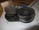
24 viewsshowing the tensioner deformed
|
|
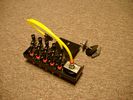
FASKIT rear showing gauge.922 views
|
|

Pass seat wiring108 viewsClose up showing the re worked Pass seat wiring on the D3 loom next to the sport one.
|
|
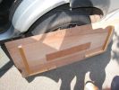
Underside showing various thickness of packing137 views
|
|
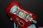
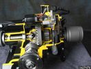
Ford 6R60 six speed cutaway showing torque converter.2198 viewsThis is a cutaway of the Ford 6R60 six speed which is a Ford license built version similar to our ZF 6HP26 six speed speced on early 3's.
The newer 3's and 4's have the ZF 6HP28. The Ford version is called the 6R80 and variations of it are used on the Raptor. As such, the Raptor metal pan can be installed on the 3's tranny but the deeper Ford Raptor pan does not have a drain plug.
|
|

First showing of Front Lamp Guards on the Discovery 4164 views
|
|

Land Rover TSB LTB00245 install instructions1939 viewsThis is the Land Rover Technical Service Bulletin showing how to install the new breather cap. The instructions are a bit vague re cutting the existing air vent tubing on a 45 degree angle with the cut facing to the rear.
|
|
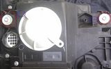
Left Headlight15 viewsLeft Xenon headlight showing adjusters
|
|
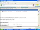
SDD hitachi file selection55 viewsSDD screen shot showing files selected with an Hitachi compressor
|
|
OE 2 cut dash showing top72 views
|
|
OE cut dash showing where to cut72 views
|
|

OE cut dash with display fitted - showing where to cut76 views
|
|

Post Suspension Calibration56 viewsA spreadsheet I made showing results of suspension calibration using Gap Diagnostics IIDTool
|
|

Pre Suspension Calibration59 viewsA spreadsheet I made showing results of suspension calibration using Gap Diagnostics IIDTool.
This is the pre-existing values
|
|
640 viewsCup holder panel showing the 8 locating lugs and clips
|
|
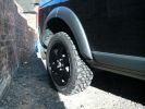
Rear Black wheel with MTR showing aggresive tread pattern543 views
|
|

Windy79 viewsPepper showing that it was windy on the Cairn
|
|

1521 viewsPicture showing two sub bass units and the computer mounted on a board in the newley aquired space.
|
|
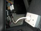
220v Socket893 viewsPicture showing the back of the Inverters 220v socket
|
|
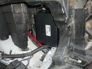
1633 viewspicture showing the location of the "Lodar" radio winch remote control box.
|
|
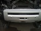
1858 viewspicture showing the finnished bumper, i think it looks quite cool
|
|
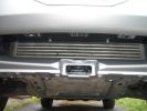
1843 viewsPicture showing no obstruction to the Intercooler, The winch is above it.
|
|
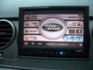
View showing media player screen2447 views
|
|
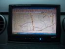
View showing nav screen.1651 views
|
|
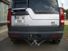
Showing rear view of the two pipes.793 views
|
|
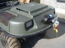
Showing 2200lb winch198 views
|
|

Showing compressor, tank, pressure switch569 views
|
|
Showing the HID ballast units575 views
|
|
Bottom of airbox, showing one-way valve and locating lug176 views
|
|
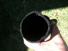
Inside factory air duct - showing felt-like material (used to absorb fumes)152 views
|
|
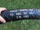
Factory air duct - showing vinyl covering154 views
|
|
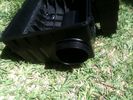
Airbox showing inner inlet tube poking through189 views
|
|

Loadspace72 viewsLoadspace showing the UK Commercial spec loaded arrangement.
|
|

iPhone Gas Cubby19 viewsScreenshot showing the fuel economy of the LR4
|
|

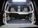
led boot space light upgrade96 viewsClose up showing how easy the led ultra bright modules fits into original housing
|
|
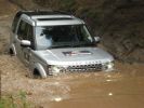
D4 showing us how it is done197 views
|
|
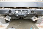
Towbar showing rear brackets554 views
|
|

D3 Rear Tailgate switch headliner connector8 viewsThe black connector in the headliner of a D3, showing the brown wire being pushed back and not making contact, and stopping the rear button from working
|
|
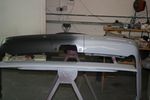
Rear Bumper Showing Lower Fixing Points83 views
|
|
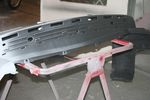
Rear Bumper High Build Primer & Showing Tread Plate Removed & Fixing Points Top84 views
|
|
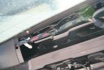
TMC amp location showing antenna button68 views
|
|
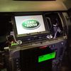
IHU and TSD14 viewsShowing boot up sequence
|
|
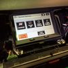
Touch Screen Display Unit13 viewsShowing menu screen shot
|
|
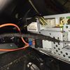
Rear of Touch Screen Display Unit12 viewsShowing connections in place
|
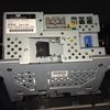
|
Rear of Touch Screen Display Unit10 viewsShowing details and connections
|
|

New pump showing reinforced casting of the tensioner mount13 views
|
|

New pump showing reinforced casting of the tensioner mount10 views
|
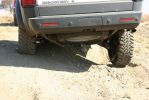
|
Richard showing some leg295 views
|
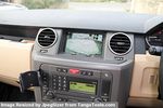
|
Sat Nav Screen showing revcersing camera view84 views
|
|

Littelfuse Add-A-Circuit MINI and ATO style data sheet150 viewsPDF from Littelfuse showing both the MINI and ATO style of fuse holders. The 3 uses the MINI size of fuse. The MINI Add-A-Circuit can be inserted in place of one of the existing fuse panel MINI fuses. The removed fuse is then inserted into the lower slot of the Add-A-Circuit and a second fuse in the second slot to protect the device that you are adding. The Add-A-Circuit is designed for a max of 10 amps on the second load, and I guess maybe the original circuit as well.
|
|

EPB Failure Analysis471 viewsDocumented dissection of failed screaming EPB showing fundamental design flaw and use of inappropriate materials.
|
|
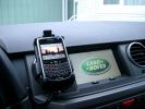
BlackBerry Tour 9630 mounted on air vent265 viewsThe antenna amplifier is mounted lower near the steering column. The amplifier box is painted black but looks sort of gold coloured due to the lighting in the other jpg showing the amp located under/near the steering column.
|
|

Interior Video Showing Full Length Rear Sunrood inside rear165 views
|
|

Video Showing Full Length Interior Rear Alpine Roof323 views
|
|

Carpet Panel Removed showing Bass Speaker and Dust Shield 1733 viewsSomething is wrong with the orientation, however this shows what you see when the carpet is removed.
The dust shield, (under which the actuator is located), in the picture is as yet uncut. The white bit is the underside of the plastic lower lift gate carpeted cover panel.
The round thing is the woofer speaker for the Harmon Kardon radio. When the radio is working, one can see the speaker moving, but not much bass sound actually seems to emanate from the speaker.
|
|
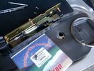
0.032" OD metal fishing leader and lead fishing weight clamped to existing wire rope 2120 viewsI used a size #0 lead fishing weight as a clamp to attach the 0.032" diameter flexible wire rope fishing leader to the release cable.
The pictured weight is the smaller #00 weight, however it did not work very well so reinstalled with the larger #0 size. I clamped to the cable as what breaks is the L retainer that is hidden in the actuator and holds the cable. When the L breaks, it lets go of the cable so you hear the clicking but there is no opening action.
Clamping on to the cable is an attempt to resolve that reality; also if the actuator electrically fails, the release mod should still do the task. Note in the picture the two Torx T15 screws that hold the gold plate to the plastic case and also the two 8mm cap screws that have to be loosened to remove the actuator from inside the door.
|
|
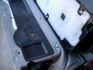
Carpeted cover removed showing uncut dust seal and underside of carpeted cover. 1628 viewsNote that there are all sorts of electrical wires sticking to the underside of the dust shield - so be very careful when you cut thru the shield.
I used a box knife very slowly and was surprised at how many conductors there were running just under the shield membrane.
|
|
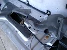
Dust seal rolled back showing electrical conductors 1658 viewsNote power conductors just under the dust seal which makes cutting the seal more interesting.
Also shown are the two 8mm nuts located in slots. One must loosen each nut to effect removal of the actuator. This will then reveal two T15 Torx screws that one must completely un-thread to remove the top gold plate from the actuator assembly.
|
|
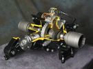
Rear Differential cutaway with E-Locker 1210 viewsThis jpg is from the link below.
There are another ten or so cutaways plus a whole file group showing a 2005 LR3 sectioned for the 2005 Chicago Auto show. Each jpg has an enlarge function to the bottom right of a main picture.
On one jpg you can see right into the stepper motor.
http://www.cutawaycreations.com/cutaways.php?project=land-rover-electronic-rear-differential#/IMAGES/car4/images/image1.jpg
Both the front and rear differentials are manufactured by Dana Spicer in the UK. Dana calls them a Clamshell design.
|
|
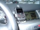
Blackberry Tour mounted on air vent showing default analogue clock 213 viewsA characteristic of the Blackberry is that when charging, the display can default to an analogue clock. Hence when the unit sits in the holder, the phone is being charged and the analogue clock displays. When the phone rings, the clock disappears and the call id displays.
|
|
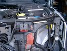
Wiring (tubing) loom at left headlight showing FASKIT panel 584 viewsThis shows the wiring (tubing) loom and FASKIT panel mounted to left wing. The loom moves a a couple of inches (50mm) towards the bottle once the headlight is put back in as there is not enough free space for the loom as located. The FASKIT panel is just visible at the top left corner of the picture.
|
|
![Filename=LR3_BMW_Ford_ZF_6HP26X-28X_Catalog_with_metal_pans_[1].pdf
Filesize=1194KB
Dimensions=320x240
Date added=26.May 2011 LR3_BMW_Ford_ZF_6HP26X-28X_Catalog_with_metal_pans_[1].pdf](images/thumb_pdf.jpg)
ZF 6HP26X and 6HP28X transmission parts showing various pans2814 viewsThis 42 page pdf is probably the most informative of all the material in this album. It is called a spare parts catalog but is much more than that. The material is specifically for the X variety of ZF six speed transmissions that are in the Land Rover 4WD / AWD models as well as BMW and Ford AWD vehicles.
|
|
Thread upload14 viewsImage uploaded in thread 169349
|
|
Thread upload10 viewsImage uploaded in thread 176633
|
|

Rosen A10 Land Rover Installation Manual841 viewsThis is a 11 page pdf which is the Land Rover version of the A10 installation manual for our 3. It consists of a hundred plus sketches showing how and where to connect various cables, conductors and plugs.
|
|
Main starting battery showing 1/2" hole drilled for power cable egress909 viewsView of OEM battery in Left Hand Drive LR3. This is supposed to be a Battery Group BCI 49 or H8 sized battery but in reality is the slightly shorter BCI 94R or H7 battery that fits easier lengthwise, (12 3/8" vs 14").
Note the 10mm hole drilled in plastic of surround to allow for entry of main power cable that runs between batteries. The cable bolts to a spare 6mm threaded hole in the OEM battery cable end; the light gauge wire runs to the front of vehicle to a connector for the CTEK MULTI US 3300 charger. Coloured felts, (red and green), are a material treated to reduce battery post corrosion. The OEM battery ground cable is only about a foot long and runs to an 8mm stud located on the inner fender just to the rear of the fuse case.
|
|
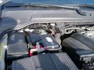
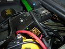
Main Battery showing aux cable feed running off positive battery post.776 viewsThe black wiring loom around the battery cable to the aux battery was a part provided with the Traxide kit. My goal was to run the cable low enough such that the battery box cover would go back on as previous.
Note the hole drilled in the side of the battery box such that the new cable could thread thru to allow the battery box top to still fit the same as prior to the addition of the cable to the auxiliary battery.
|
|
Thread upload54 viewsImage uploaded in thread 52879
|
|

NAS 7 plus 4 pin LR3 Trailer wiring, trailer end. 498 viewsThis is the LR wiring diagram showing the conductors from the the Trailer Brake Controller connector, C2590, back to the rear combo NAS 7 plus 4 pin sockets.
|
|
144 views
|
|

Crop from LR Driving Liight fitting instructions showing Nudge Bar bracket410 views
|
|
Thread upload1 viewsImage uploaded in new thread
|
|
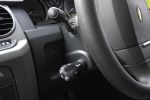
Goldcruise control showing presets, fitted to LHD key blank484 views
|
|
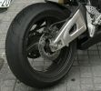
Closeup View - Honda CBR193 viewsShowing feathered edge on a bike that is obviously ridden like the rider stole it!
|
|
cross view showing access hole505 viewsCross view of the 1.25" inch access hole. You can reach your finger or a screwdriver in this hole to move the lever up or down. It will be fitted with a rubber plug when not in use (and when found)
|
|
Traxide SC80-LR mounted598 viewsA close up showing the angle, mounting bolt. Only a single top bolt can be used, there are metal lines behind the lower bolt hole.
|
|
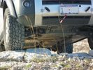
Rover Specialties Rock Sliders258 viewsRover Specialties Rock Sliders showing compressor protection
|
|
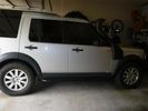
GNV Rods fitted932 viewsThis is the "normal" height showing clearance after fitting the GNV Rods. A slightly noticeable height improvement, but not so much as to be too much.
|
|
D44 Winch stainless fairlead492 viewsTop view showing the neat and tidy fit and finish, no knee bumpers here.
|
|
Back of A post trim showing how windscreen ticket holder attaches362 views
|
|
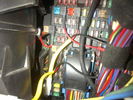
Fuse Panel showing F35P Add A Circuit installed1241 viewsFive amp fuse F35P is located towards the top left in this jpg. The other three Add A Circuit devices are for other items - powering my cell phone base etc.
Note the orientation of the Add A Circuit as this matters. Also one can just see a red tab sticking out from behind the device. The red is the conductor crimp end of a narrow 2.8mm male spade type connector that inserts into one of the "fuse" slots.
|
|
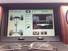
Display showing suspension lowering!23 views
|
|
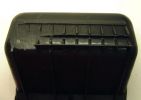
Pocket removed - showing rear bottom where bonded to dash63 views
|
|
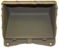
Pocket removed - showing cut along the moulded top section69 views
|
|
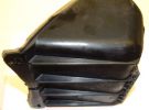
Pocket removed - showing bottom side62 views
|
|
Showing the 500mm SMD LED Strip Light (6.5 watts)115 views
|
|
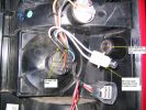
Rear light showing new bulb holder and connections430 views
|
|
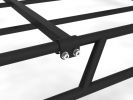
Close up of cross bar fixings263 viewsClose up showing how our crossbars fit our rack
|
|
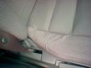
S Seat showing wear at 12 months old367 views
|
|
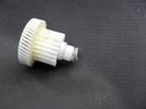
The faulty unit (secondary gear / torque clutch)376 viewsShowing the inadequate circlip retaining land, ripped iopen by the normal spring tension. Should never have been made of plastic...
|
|
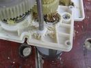
Gear box casing showing wear from screaming friction...409 views...once the circlip has bust through the inadequate retaining land, the spring presses on the (other) gearbox casing, forcing the secondary gear to wear on the gear box casing where shown, there being no adequate provision for end-thrust (even though helical gearing would mandate that, to cope with the NORMAL axial vector forces produced) resulting from spring pressure on the other gearbox casing face pushing the gear into this face.
|
|

25 viewsshowing the fixed tensioner on the upper right of the engine
|
|
N/S and brackets showing 6 x 10mm bolt fixings162 views
|
|

Thread upload6 viewsImage uploaded in thread 143566
|
|
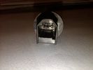
sunlight sensor93 viewssunlight sensor bottom sight showing three connection pins
|
|
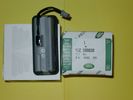
Upper Hatch Release Switch LR Part Number YUZ500020676 viewsThis is the Range Rover Sport switch, Land Rover part number YUZ500020, as it comes out of the box. Note the JAE, (Japanese Aviation Electronics), male wiring connector installed on the end of the power lead.
The rubber cover of the switch is sealed to the plastic body of the switch whereas in the previous switch design, there was no sealing. Also the replaced switch was hard wired into the same harness as the license plate lights - no JAE connector in other words.
|
|
TDv6 Oil dip stick280 viewsPhoto shows oil level on rear stick (cleaned front stick). Note that diesel oil when fresh may not be black like the sample shown (car had travelled 5 000km on delivery oil). You can see small indentations in both sticks. This is where I observe the current oil level. Note also the two arrows at either end of the red plastic indicators showing lower and upper limits (I do not know what the red ball is for however - it just may be a guide.)
|
|
Temperature / humidity sensor91 viewsTemperature / humidity sensor fro the rear showing the two connecting pins
|
|
Thursday Suspension Height151 viewsSecond of two photos showing my suspension had dropped by nearly two inches in just over three days sat on the drive
|
|

Troubleshooting pdf re Mechatronic unit on 6HP26 ZF Automatic 2144 viewsThis 21 page pdf shows possible problems within the Mechatronic unit of the ZF 6HP26 six speed automatic. On page 19/21 is a drawing showing how all the various control circuits interface with the vehicle.
Of particular interest were comments with regards to fine metal contamination of various electrical contacts. This is probably why a mere oil change can improve the operation of the transmission - reduced conductivity of the oil.
|
|

ZF Transmission parts exploded views1292 viewsA 35 page pdf showing exploded views of the inside of the transmission along with oil fill procedures and part numbers. There is also the suggestion of a metal pan but no part number given and the appearance of a more usual type of oil pan gasket, flat rather than O ring.
|
|

Underside of ZF 6HP19 and 26 transmissions pans1428 viewsThis is a view of the underside of two different plastic transmission pans, one for the ZF 6HP19, and the other, the 6HP26.
The 24 Torx screw pan is for the 6HP19; the 21 Torx screw pan is for the 6HP26/28/32 transmissions. The screws are numbered in the order that they are to be tightened re the O ring seal. Our 3 has the 21 screw transmission, the ZF 6HP26X six speed.
|
|

Mechatronic Replacement Hints plus drains for steel and plastic pans1111 viewsThis 22 page pdf shows colour views of the Mechatronic unit as well as good illustrations of the drain and fill ports in both the plastic, page 17, and steel pans, page 18.
Page 8 details the replacement of the sealing sleeve where the electric wire feed thru the case into the Mechatronic unit. The seal is normally replaced when a new pan is installed as the seal is a known leakage point.
|
|
|
|