| Search results - "supposed" |

Rear Area Climate Control System1161 viewsThis 14 page pdf describes how the rear heating AC system is supposed to operate in conjunction with the front system.
The air transfer ducts are shown as coloured sketches as is the air flow within the rear blower setup.
|
|

Air Conditioning and Heater Control Components2425 viewsThis is a 21 page pdf that really explains how the air system is supposed to work. Discussed are the exterior ambient air sensor, where and how it operates; the interior temperature sensor as well as humidity sensor.
|
|

Alarm System description and Operation1052 viewsThis 9 page pdf explains in detail how the anti-thief, (alarm), system is supposed to operate. The system uses the door ajar switches to provide alarm system signals; as such there are few separate contacts related to the alarm system only.
Page 6 of 9 is of particular interest as it describes the trigger log that is accessible with the dealer T4.
|
|
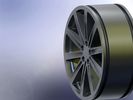
CAD render of a rim I created.71 viewsCAD render of a rim I created. Was supposed to look like the 18" style 2 rims.
|
|

Brake Light Switch, Find, Remove, and Install Instructions 7852 viewsThis is a two page doc outlining where to find the brake light switch, how to remove it, and then install the new one.
Note, do not move the brake pedal when removing or installing the switch. Let the brake pedal hang where it wants to. The switch design is actually cunning, and as such is supposed to make the removal and install fool proof. Hence if you think too much about it, you can wreck the new switch.
If you want to inspect the interior of the switch, wait until you have removed the old switch. You can then just unsnap the blue from the white to get it apart. Inside, the switch is quite simple, (no circuit boards), but it will probably show black dust from failing contacts.
I think the reason the switch fails is that the Normally Open, (NO), contacts of the brake light contacts were made too light to carry the current load for make and break of the tail light filaments. I also think the black dust created then fouls the Normally Closed, (NC), second set of contacts for the ABS circuit. As such, the Normally Closed contacts become intermittent in operation and display as a fluctuating open and closed circuit condition to the ABS system when the ABS should be seeing a steady closed circuit. Hopefully the replacement switch contacts are more robust and may be as I recently replaced my switch again just as a matter of maintenance. While in a redesign, ideally the NC contacts should be sealed or at least separated from the NO contacts, when I inspected the removed switch, this time there was no black dust present.
Probably the removed switch will have a Land Rover oval logo moulded into it, the new one, FOMOCO.
|
|

Central Door Locking Operation Description1458 viewsThis 17 page pdf explains how the door locks are supposed to operate. Note that on page 9/17, the explanation of the operation of the hood ajar switch is wrong. It operates similar to the door and tailgate ajar switches; that is when a "door" is closed, the switch is closed to maintain a ground back to the CJB. Opening the hood, door, or tailgate removes the ground breaking the circuit and hence allows for an alarm condition.
|
|
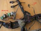
example problems113 viewsInspection showed another Cut Airbag connector, a Missing connector and a few rogue wires at the bottom, the silver one marked Lin, is for the LIN BUS and is supposed to be like that though
|
|

CAD render of a rim I created67 viewsCAD render of a rim I created. Was supposed to look like the 18" style 2 rims.
|
|

Fuel Purge Valve and other hoses.846 viewsThis 6 page pdf shows the Fuel Purge Valve and associated hoses and describes how it is supposed to work. There are lots of good drawings of the fuel system. It is more complicated than one might think.
|
|
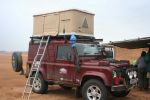
I thought it was supposed to be hot and dry in the ressert256 views
|
|

Air Suspension System Parts, Layout, and Operation7062 viewsThis 22 page pdf gives a pretty good description of how the system is supposed to work, plus shows the various parts and the electrical including fuses and relays etc. Of the files here, this is the most useful.
As with all the pdf's here, you can download and print it out.
|
|

NAS 7 Pin Round Socket + 4 Pin Flat Socket oriented as installed.752 viewsThis is the layout you see when you look into the NAS Land Rover sockets as installed at the rear of the LR3/4. The flat 4 pin socket is located under the round socket.
Wiring order is relative to the slot on the round socket, and hence the same as the other jpg where the slot is shown at the top.
The CJB monitors the front and rear turn signal lamps and can detect if more than four lamps are fitted, (the side turn signal lamps are not monitored). This is another reason for using genuine LR bulbs as off shore bulbs can have varied and out of spec resistance values.
When a trailer is detected, the trailer warning indicator in the instrument cluster is supposed to flash green in synchronization with the turn signal indicators.
If one or more of the turn signal lamps on the vehicle or the trailer are defective, the trailer warning indicator will cease to flash any longer. This is to alert the driver to probably bulb failure.
If the trailer has LED lamps installed, and no LED adapter circuitry is used, most likely the trailer will not be sensed and systems such as the backup sensors will not be disabled.
|
|

Fuel Tank Internals, Description and Operation 809 viewsThis 10 page pdf shows views of the fuel tank internals, what the various pieces do and describes how the fuel storage system is supposed to operate.
As usual, you can download it, save, and print as required.
|
|
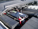
Main starting battery showing 1/2" hole drilled for power cable egress909 viewsView of OEM battery in Left Hand Drive LR3. This is supposed to be a Battery Group BCI 49 or H8 sized battery but in reality is the slightly shorter BCI 94R or H7 battery that fits easier lengthwise, (12 3/8" vs 14").
Note the 10mm hole drilled in plastic of surround to allow for entry of main power cable that runs between batteries. The cable bolts to a spare 6mm threaded hole in the OEM battery cable end; the light gauge wire runs to the front of vehicle to a connector for the CTEK MULTI US 3300 charger. Coloured felts, (red and green), are a material treated to reduce battery post corrosion. The OEM battery ground cable is only about a foot long and runs to an 8mm stud located on the inner fender just to the rear of the fuse case.
|
|
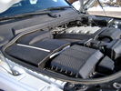
Overview of engine compartment from Main Battery side, (Passenger, LHD), looking across to Aux Battery752 viewsNote labels on main battery cover. The one you cannot read says that an auxiliary battery is installed on the other side. This is to warn service people should they wish to shut off all battery power.
The main starting battery is supposed to be of CaCa separator construction and DIN H8 or BCI Group 49 size. This means Calcium separators Wet Flooded Lead Acid, 13.9" long, 7.5" high and 6.9" wide.
On the Aux battery cover is a label saying to disconnect the blue Anderson single pole connector located under the cover by the brake reservoir. BCI Group 40R battery is small enough that the cover goes back on.
|
|
|
|
|