| Search results - "term" |
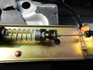
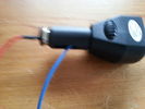
Cavo nel morsetto - Cable in clamp48 viewsHo inserito il terminale rotto nel morsetto: bisogna sforzarlo molto e ho praticato una cava attraverso il foro della vite con una punta in modo che il terminale non possa scivolare.
I entered the terminal broke into the clamp: you have to force it a lot, and I practiced a quarry through the screw hole with a bit so that the terminal can not slip.
|
|
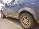
Aftermath #2124 views
|
|
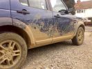
The aftermath at home #1127 views
|
|

12S plug from eBay and Ctek lead (provided with MXS-10) - before cutting the ring terminals off.28 views
|
|
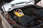
124 viewsOptima Yellow Top in battery box. This is the version with side terminals so there will be some modifications to be done to fit
|
|
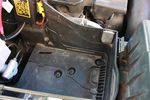
112 viewsDue to the side terminals protruding out the side and affecting the battery clamp, I found the battery will fit better if it could be pushed a few millimeters towards the engine. This lip will have to be removed.
|
|

91 viewsBattery clamp needs to be modified due to the mouldings on the battery top to the side terminals. All that is needed is to cut off the bit as seen.
|
|
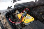
131 viewsBattery clamped down, terminals and cables attached
|
|
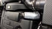
Thread upload148 viewsTemporary short term fix - duck tape to get you home!!
|
|
Terminal7 views
|
|
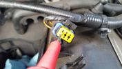
Test probe measure voltage18 viewsDo NOT insert the test probe into the connector as this can damage the terminal.
|
|

Thread upload22 viewsImage uploaded in thread 184721
|
|

Thread upload22 viewsImage uploaded in thread 184721
|
|

Thread upload23 viewsImage uploaded in thread 184721
|
|
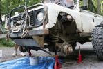
aftermath319 views
|
|

Thread upload0 viewsImage uploaded in new thread
|
|
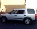
After Side Protection and Tints127 views
|
|
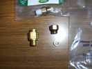
Air Parts57 viewsSubstitue push fit air spring terminators for Disco 3
|
|

Alternator female plug looking down into top373 viewsThis shows the plug connected to the alternator wiring harness looking down into the top of the plug.
The cavity marked 1 is the AS or BATT SENSE and the wire colour most likely has Brown/Green on it.
The cavity marked 2 is the RC or ALT CON and the wire colour most likely has Red/White on it.
The cavity marked 3 is the L1 or ALT MON and the wire colour likely has Green/White on it.
I say "most likely" as the wire colours are not always the same on all vehicles.
Also the terminal 1 conductor destination is more likely C0570-175 rather than per the jpg.
The #3 pin is located closest to the big B+ terminal.
|
|
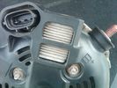
Alternator Plug and B+ terminal918 viewsPictured is the rear of the older Land Rover part # YLE500190 alternator showing the shiny cooling fin of the Regitar VRH2005-142 regulator under.
The first pin in the far left side of the connector is numbered #1 in the LR electrical wiring diagrams and is Battery Voltage Sensing (BVS); the middle pin, #2 receives a Pulse Width Modulated (PWM) signal from the Engine Control Module (ECM), and the right pin, #3 carries a PWM signal back to the ECM. Terminal Pin #2 on the LR wiring diagrams is called Alternator Control or ALT CON; Pin #3 per LR is called Alternator Monitoring or ALT MON.
Pin #1 is similar to what in older designs used to be called A or Batt, but is now called by Denso, S, AS, or Alternator Sensing for this design. Pin #1 also provides power to excite the alternator at startup until the PWM instructions over ride the battery voltage info. Land Rover calls the electronics under the pins a Smart Regulator, ironic, as it has to follow orders from the ECM rather than give the orders - new age thinking I guess. This is different from older design internal regulators that look at just the battery or the electrical buss voltage and then decides itself what to do.
It is almost like we are back to the external regulator designs of old, except that the ECM may decide that instead of telling the alternator to make more power, to load shed, and hence shut down the heated windscreen, seats, or whatever other electrical loads it decides are appropriate. My view is that the "smarts" are in the ECM and that the "regulator" should be regarded if not dumb, then as being a slave to the ECM.
|
|
Thread upload18 viewsImage uploaded in new thread
|
|
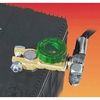
Battery Disconnect Wirthco 20308 Knob Top Post 890 viewsThis is a battery post style disconnect, usually for the negative terminal. There is a hole drilled in the round end off the battery so that flat terminal can be attached as well as the normal battery post terminal. I did not use this hookup arrangement, however I show it for information only.
|
|
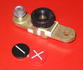
Battery Disconnect side post with + & - caps, top view617 viewsThis disconnect is designed for side post batteries. It can be used on either the + or - terminals. It can also be installed at the "other" end of the battery cable as well. In my install of the Aux battery, I installed this on the negative ground cable where the cable attaches to the body sheet metal. I have never used it but it seemed like a good idea at the time. The main battery hookup is pure stock.
For the hot side of the Aux battery, an Anderson PowerPole was used inline for the cable between the Aux and connecting to the spare bolt hole at the + post of the Main battery cable.
|
|

Thread upload4 viewsImage uploaded in thread 180189
|
|

Positive battery terminal lead15 views
|
|

Brake Light Switch, Find, Remove, and Install Instructions 7853 viewsThis is a two page doc outlining where to find the brake light switch, how to remove it, and then install the new one.
Note, do not move the brake pedal when removing or installing the switch. Let the brake pedal hang where it wants to. The switch design is actually cunning, and as such is supposed to make the removal and install fool proof. Hence if you think too much about it, you can wreck the new switch.
If you want to inspect the interior of the switch, wait until you have removed the old switch. You can then just unsnap the blue from the white to get it apart. Inside, the switch is quite simple, (no circuit boards), but it will probably show black dust from failing contacts.
I think the reason the switch fails is that the Normally Open, (NO), contacts of the brake light contacts were made too light to carry the current load for make and break of the tail light filaments. I also think the black dust created then fouls the Normally Closed, (NC), second set of contacts for the ABS circuit. As such, the Normally Closed contacts become intermittent in operation and display as a fluctuating open and closed circuit condition to the ABS system when the ABS should be seeing a steady closed circuit. Hopefully the replacement switch contacts are more robust and may be as I recently replaced my switch again just as a matter of maintenance. While in a redesign, ideally the NC contacts should be sealed or at least separated from the NO contacts, when I inspected the removed switch, this time there was no black dust present.
Probably the removed switch will have a Land Rover oval logo moulded into it, the new one, FOMOCO.
|
|

Copley 4x4 prepaid service agreement brochure109 viewsWord doc with image of brochure
|
|
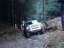
Determined..278 views
|
|

My Defender22 viewsDefender TD5 looking to keep it long term with a chassis replacement this year.but the quality / ride contrast between it and our Disco 3 is very apparent.
|
|

Thread upload28 viewsImage uploaded in thread 171332
|
|
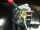
190 viewssignal wire pin 3 on rear of D4 rear light plug fit 6 ohm 50 watt resistor across here and common ground Pin 5 yellow terminal shown in next pic
|
|

Exterior Lighting - D3159 viewsSource is undetermined
|
|
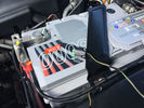
Thread upload9 viewsImage uploaded in new thread
|
|

Buttermere68 views
|
|

Monitor per retrocamera48 viewsNavigatore aftermarket con schermo da 6"
|
|
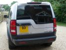
Disco3 sticker206 viewsExtermal dark grey sticker
|
|
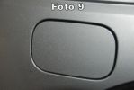
Foto 9 - Portello chiuso e riparato102 viewsIl portello � finalmente riparato. Personalmente ho impiegato circa 1,5 ore per terminare il lavoro, tenendo conto che non conoscendo il meccanismo ho smontato completamente il pezzo dall\'auto. Smontando solamente il pezzettino rotto ed avendo a disposizione l\'occorrente in non pi� di un\'ora il portello � riparato.
Ora tocca al posacenere che non si chiude pi�, il colmo � che non fumo e dal 2005 ad oggi l\'avr� aperto 5 volte!!
Saluti e buon lavoro (sempre a vostro rischio e pericolo).
|
|
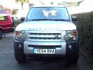
Meet "Arnie"711 viewsThe kids have named him Arnie - as in Schwarzenegger - because it looks 'mean' - a hint of the terminator there!.
|
|

105 views
|
|

Thread upload9 viewsImage uploaded in thread 149176
|
|
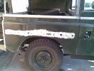
terminal corrosion35 views
|
|
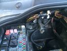
Harness location15 viewsArea of harness that chafes against battery terminal
|
|

EAS Aftermarket Modification.24 viewshttp://www.mudtech4x4.com
|
|
D4 detail10 viewsThe grill was one of the determining factors
|
|

PP002 12V135 views Brad Harris Socket
Hella Socket Cigarette
Lighter Socket
Battery Level Meter
External Terminals for Battery Charger or Solar Panel
ON/OFF isolator tie down strap excludes Battery
Built in fuses
https://www.facebook.com/snomasterusa
|
|

Floating Caravan - Gunwharf Quays, Portsmouth 64 viewsHalf term happy families....
|
|

Partial remains of battery terminal bolt - Oops20 views
|
|
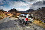
CALENDAR 2011454 viewsButtermere
|
|

Thread upload4 viewsImage uploaded in thread 178284
|
|
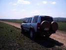
D3 in Litchfield National Park, on the Reynolds Track44 viewsThis track takes you through the bottom half og the Litcfield National Park, and because the track has some deep creek crossings it keeps the numbers down, seeing as it is only 90 minutes out of Darwin. It is a flood plain between two long ranges and has numerous \'Magnetic termite\' Mounds.
|
|

Wheel cut thru definitions and specs898 viewsNote the location of REAR SPACING and also OFFSET; probably two of the most important dimensions and not always understood as related to wheel size and relationship to the brake components.
For the 3, Rear Spacing is approximately 6.5 inches or 165 mm for a nominal 8" rim. Offset is 53P or 53mm Positive, which means the distance from the machined hub flat mounting surface to the rim's true centreline is 53 mm in the outboard direction. (The rim illustrated has a negative offset.)
As Positive offset increases, this means the wheel wraps around the disc brake mechanism more deeply, and hence the more the wheel would cover the brake parts. This is why most 18" wheels will not fit with the larger Brembo "supercharged engine" brake calipers.
Pitch circle diameter is 120mm; Pattern is 5 lug, and the tyre load rating is 112 with a recommended tyre speed rating of H or higher along with the XL load rating. For the 3, the stock tyre diameter is about 30 inches. The 255/60/18 or 255/55/19 OEM tyre outside diameter is 30.04 inches; Wheel lug torque is from 130 to 150 Nm or 96 to 110 lbf-ft and the lug nut hex socket size is 22mm.
Max Load High Speed Driving Tyre pressures are Front, 33 psig, (230 Kpa) and Rear, 42 psig, (290 Kpa).
The OEM rims are rated at 940 kgs, the highest that LR makes, hence while rims from other Land Rover products may physically fit, the odds are they are under rated in a weight sense.
|
|

LR3 Denso Alternator YLE500390 pulley view819 viewsNote the DENSO sticker on the side. Denso calls their nominal 150 amp 12 Volt alternator an SC2 design. SC means Segment Conductor which apparently increase the winding density of the stator coil, hence yielding a physically smaller lighter alternator for a given output. I presume the 2 means the second try at getting it right. A Denso part number is 4280003690 for the alternator, (there are others, as below).
Rotation is clockwise and the 54mm diameter pulley has 6 grooves (PV6x54). Count the pulley grooves on both the one you remove and your new one - some replacement alternators seem to ship with 5 or 7 grooves so you might be swapping pulleys.
A previous LR part number was YLE500190 for the older variation of the newer YLE500390 unit.
An additional part number for a factory rebuilt is Nippon Denso 210-0569 for the petrol V8 alternator. Other Nippon Denso numbers include 104210-3690 and 104210-3691. The Lester number is 11206 which relates to another Denso number of 290-5287. WAI uses 11206N.
From 2006 to 2009, the internal regulator is a Transpo IN6349 and of the B circuit type if it can be said that applies to PWM, (Pulse Width Modulated), regulators.
The "regulator" inside the alternator is therefore really not a regulator in the old sense of the term but instead an instruction receiver from the ECM that translates Pulse Width Modulated (PWM) signals into a form that the alternator understands – digital like signals from the Engine Control Module(ECM) into analogue like signals that the windings understand.
|
|
Thread upload1 viewsImage uploaded in thread 196420
|
|

Thread upload9 viewsImage uploaded in thread 165866
|
|

cratermass20 views
|
|

How to cable factory BT module (including MOST bus connector)85 viewsInstructions to install Factory BT module in a Disco 3 that has LR aftermarket or no BT module installed
|
|

Thread upload14 viewsImage uploaded in thread 174113
|
|

65 views
|
|

Thread upload6 viewsImage uploaded in thread 207513
|
|
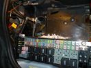
Battery Box Primary186 viewsThis visual is what is next to, behind and under your battery. It is important to note that the negative terminal which is prone to corrosion is in the rear, nearest to everything to maximize damage. The white powder pictured is baking soda. This is carefully used with a damp rag to neutralize any effect of battery acid (hydrochloric acid).
|
|
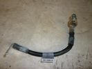
Negative Battery Cable208 viewsThis shows the corrosion from the negative terminal on the Negative to body ground. This is likely due to gas released through the negative post. It appears to be a common problem with the LR3. As a result of this corrosion left unchecked will damage the computer ecu and cables mounted near and below the battery.
|
|
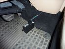
connectivity module59 viewsthis part is used for the aftermarket kit and will be removed
|
|
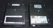
aftermarket and factory BT module56 viewsnotice the additional MOST connector (with white protective cap) for the factory install module
|
|
Parcheggio dopo termine prima parte - Castello di Zumelle201 views
|
|
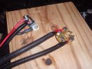
New battery terminals69 views
|
|
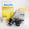
Philips D2S 85122 C1 Xenon 4300K projector HID bulb962 viewsThis is the 4300K OEM bulb in our HID Xenon projector headlights. People who design illumination systems regard the 4300K colour as a good compromise to provide what is called definition. This is effectively the ability to actually determine what an object being illuminated probably is. The more blue colour bulbs, say 5000K and greater, result in a reduction in the ability to distinguish detail, (regardless of brightness), of the object being illuminated. Effectively, you can see the object but you cannot quite figure out what it is. This is because the more blue frequencies means there are fewer other frequencies of light that allow our eyes to actually discern what an object really is.
The 4300K colour temperature applies to clear air conditions; for rain, dust, snow, fog, etc, then a yellow 2500K colour temperature is preferable. 2500K provides more contrast and there is less back splash of light off the air particles. In blowing snow, this means less sparkle back. Flat top cut off of the light beam, (which is the pattern our projector lights have), is important to reducing back splash - hence you do do not want roof mounted lighting for adverse conditions - as low down as possible is preferable, (which is why fog lights generally sit low.)
|
|
Thread upload3 viewsImage uploaded in thread 195235
|
|
Thread upload3 viewsImage uploaded in new thread
|
|
73 views
|
|

Transpo pdf explaining the operation of Ford PWM regulators624 viewsThe 4 page pdf produced by WAI-Transpo explains the operation of the Pulse Width Modulated regulators located within the alternators on our 3's. Of note, the pdf states that certain of the Ford PWM regulators do not meet Ford spec.
The pdf explains the function of all the terminals and the apparent advantages of the PWM style over previous designs. Note that Ford calls their "engine computer" a PCM, (Power Control Module), whereas Land Rover, an ECM, (Engine Control Module).
|
|
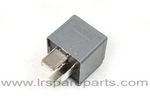
Air Compressor 70 amp replacement relay1393 viewsThere is a software update, 09 April 2010, LTB00270, for the compressor which reduces the shut down pressure to about 205 psig (14 bar). The update is usually done when changing to a new compressor and also includes replacing the R7 relay in the engine compartment fuse box, 07 DEC 2010 LTB00331.
The newer grey case coloured relay, part # YWB500220, shows to be rated at 70 amps, (the relay, not the compressor), however the previous black case coloured relay also indicates 70 amps.
Both the new and replaced relay show on their wiring diagrams to have a parallel voltage spike resistor, (probably 560 ohms), across the coil terminals, #1 and #2. This means one does not just replace the relay with any four prong 70 amp ISO sized relay that one happens upon.
One presumes the grey relay is either upgraded or just being installed for good measure. The relay is common on Ford Fiesta for the seat heater relay, Ford part number 5M5T 14B 192 EA; also Volvo, part number 30765034. The Tyco part number moulded on the grey body is V23136-J4-X62.
|
|
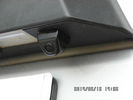
Tailgate Camera located above license plate.598 viewsThis aftermarket camera is mounted on my 2005 LR3 in almost the same location as the factory cameras. The factory units are mounted somewhat more forward closer to the metal of the tail gate and I could have done the same as well.
Note that the camera above is aimed a bit towards the centreline of the vehicle per the factory install.
|
|

My old Seadoo RXT 291 viewsOn holiday with the ski's, St Tropez France.
My RXT on the left, supercharged & intercooled 1500cc rotax engine...aftermarket freeflow intake system by RIVA, SOLAS blueprinted prop, race sponsons, RIVA intake grate & opas system removed for less drag...estimated 230hp.
Proven 70mph (with GPS & Radar gun)
On the right is my best man's GTX Ltd. with 185hp and good for 60mph with a tail wind...
|
|
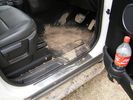
Caked-on mud aftermath80 views
|
|

Thread upload11 viewsImage uploaded in thread 141923
|
|

Thread upload5 viewsImage uploaded in thread 202761
|
|

Thread upload3 viewsImage uploaded in thread 202761
|
|
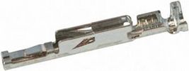
terminal,most used in D337 views
|
|

Termite mound 11 viewsNow that's what you call a Termite mound
|
|

Thread upload5 viewsImage uploaded in thread 106191
|
|

Thread upload5 viewsImage uploaded in thread 106191
|
|
Thread upload45 viewsImage uploaded in new thread
|
|
Thread upload4 viewsImage uploaded in thread 153074
|
|

Dune Descent92 viewsNo picture seems to do sand dunes justice in terms of their scale and beauty. This was a 100 metre dune (according to the GPS track profile anyway)in the driest, softest sand that behaved like a liquid as you descend the slope. Low 1st, DSC and HDC off and feathering the throttle was the technique used and the descent happens under full control.
|
|
275 views
|
|
|
|
|
|
|