| Search results - "that" |
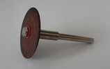
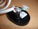
Disco abrasivo - Abrasive disc20 viewsDeclino ogni responsabilità per i danni che eventualmente farete direttamente o indirettamente seguendo questi consigli.
Per aprire la chiave ho usato un disco abrasivo da modellismo montato su un minitrapano. Deve giare velocemente.
Decline all responsibility for any damage that may directly or indirectly do by following these tips.
To open the key I used an abrasive disc mounted on a mini-drill. It must turn quickly.
|
|

Lining Up Before the Event375 views10 trucks in all - 2 Heavily modded D2s, modded 03 D2, 90' RRC, lifted P38 on ATs, my LR3, modded D1, an older CJ, a Rubi that joined, and a Series III!
|
|
Everyone heard that DG was at the bar161 views
|
|
Told that I had to test the ladder, and there aint no better test than sticking me up there!184 views
|
|
02 Last Photo before the little wheel problem saga222 viewsThis is my D3 with trailer on the banks of the Darling River, literally "back of Bourke" (the regional definition of the start of the Australian Outback). We were the first vehicle in a week to try and drive this route from Bourke to Wilcannia on the account of floods (first water in 7 years). Little did we know that 3 hours later there\'d be a bit of a wheel and tyre problem appearing...
|
|
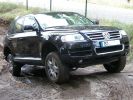
241 viewsThis Toureg is stuck - doesn´t look like it. After 8 hours of driving everyone agreed that with the big 10cyl. diesel engine you should probably oder the rear difflock as well... In this picture the rear left anf front right wheels have no grip, esp or whatever just doesn´t do it.
|
|

That WAS steep!138 views
|
|
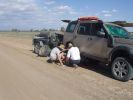
03 First bit of tyre/wheel trouble245 viewsIn the outback a tyre suddenly blew. "No worries" we thought, as we had 3 spares (+ two more if we abandoned the trailer), 150l of water, 3 days of food, and an EPIRB if things got really bad. At the time I didn\'t fully appreciate the fact that my index got a blister from the burning heat of one of the wheel nuts. It was 45 deg C at the time, so everything was hot.
|
|
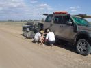
03 The first bit of tyre/wheel problem251 viewsSomewhere in the Australian outback on a 45 deg C day in Jan 08, a D3 had a bit of a flat tyre problem. "No worries, mate" st we had 3 spares (plus 2 more if we abandon the trailer), 150l of water, 4 days of food, and an EPIRB if things really go crook. The first clue that this was not a "normal" flat was when I handled a wheel nut and ended up with a blister from a burning hot nut (the ambient wasn\'t THAT hot).
|
|
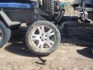
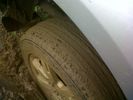
04 Damaged Tyre301 viewsYes, there\'s no doubt that this was a flat tyre. The ultra hot wheel nuts, look of the flat (note in a later photo that the back of the tyre appeared okay) and increased fuel consumption should have been a clue, but it was 45 deg C, and we had been doing about 105 km/hr on a dirt road for hours, so we just assumed it was a flat = WRONGO!
|
|
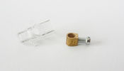
Morsetto - Clamp33 viewsHo smontato il morsetto, il diametro del foro è esattamente quello di quello che rimane del particolare che si è rotto.
I removed the clamp, the hole diameter it's the same of the detail that is broken.
|
|
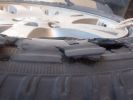
05 No doubt the tyre is flat275 viewsThis is the view of the flat tyre. Again, didn\'t think it anything more than a "normal" explosive blowout, as the tyre was about 90% worn, we were heavily loaded, it was 45 deg C, and driving 105 km/ho on a rough dirt road in the outback.
|
|
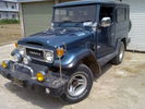
Seriously....anyone want to mess with that bumper71 views
|
|
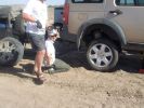
06 Spare tyre on and still suffering from hot wheel nuts296 viewsManaged to get ultra hot wheel nuts back on the spare (using the original 19" D3 wheel, vs the 19" RRS wider wheel which blew - shown in left of photo). Pity we didn\'t note that the disk brake was EXTREMELY hot at this time.
|
|

07 Back side of failed tyre340 viewsThis is the back of the blown tyre. It looks like any other worn tyre which has run a bit while flat. Note that we were running on wider 19" RRS wheels (have 4 19" MTRs + 1 old A/T on the original 5 wheels). Also have a rear-mount spare tyre holder which is really convenient with the wider rim and the fact that the tyre was still hot (it had some melted rubber on the other side!!)
|
|
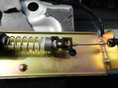
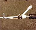
Cavo nel morsetto - Cable in clamp48 viewsHo inserito il terminale rotto nel morsetto: bisogna sforzarlo molto e ho praticato una cava attraverso il foro della vite con una punta in modo che il terminale non possa scivolare.
I entered the terminal broke into the clamp: you have to force it a lot, and I practiced a quarry through the screw hole with a bit so that the terminal can not slip.
|
|

"thats my boy"tintagel castle 2009105 views
|
|
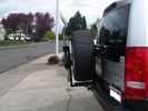
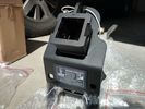
Receiver for toy rack39 viewsSensor bar was made of same heavy tube that the carrier was made from allowing a small 1 1/4" receiver to be placed on it for a multitude of toy racks of my choice. Rack adjust in and out of receiver.
|
|
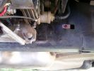
Repositioned compressor bracket738 viewsThe bracket was snapped in two, so I had it re-welded and slotted out the mounting holes so that it could be positioned 10mm higher (no longer protrudes under the chassis rail)
|
|
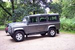
New Defender41 viewsNew Defender at National Trust park on route back home.
You can tell its new, its too shiny. Never looked like that again!
|
|
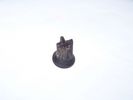
sunroof drain grommet - piece that broke off61 views
|
|
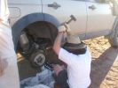
11 Lesson in removing a jammed brake assembly in the Outback378 viewsSpent the next 4 hours doing this to my D3. Gave the photos to Land Rover dealer and they did not think this constituted abuse of the vehicle. I thought that was charitable, but if we hadn\'t done this, the tow back to civilisation would have been even longer.
|
|
![Filename=15082008064 [640x480].jpg
Filesize=73KB
Dimensions=640x480
Date added=15.Aug 2008 15082008064 [640x480].jpg](albums/userpics/12862/thumb_15082008064%20%5B640x480%5D.jpg)
In Disgrace100 viewsThis is where its been for 3 weeks &3 days waiting for the parts to arrive from England. later that afternoon we aere able to take her home. Civilation at last :)
|
|
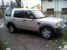
Suspension dragster mode442 viewsAfter I succesfully changed my wintertyres to summertyres, I found out that the front suspension was on access level and rear at off-road. Situation cleared after I switched engine on.
|
|
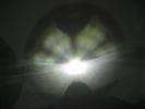
This is a normal H7 HID bulb installed in a BMW headlight to show glare above cut off line99 viewsThis is what the light pattern is that causes glare in most retofit applications including some projector lights. this is in fact a projector headlight on a BMW but the old projectors were only actually half projectors and half reflective bowls. the beam pattern should be clean cut like this ___/
|
|
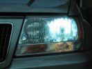
Standard hid bulb - light everywhere and glare caused by light in bottom of bowl96 viewsWhilst the beam pattern is ok the problm is that with 300% more light the spillage into the bottom of the reflector bowl is seen as glare by other motorists. it also is the reason the overhead motorway signs are lit up so well be bad retrofit xenons
|
|
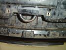
Rivetted in bracket, showing tabs that will be sandwiched by the plate95 views
|
|

On top at last351 viewsPhoto at the sumit of Arigna mountains, as part of one of the stages in the 2009 4x4challenge in aid of Temple St childrens hospital. Tough gettin there especially as we towed a Deafner90 up behind us that had bursted an expansion bottle. But the D3 powered on up regardless.
|
|

That's why there is a Detour - Simpson Desert25 views
|
|
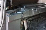
91 views12V socket done. This is permanently powered by the Aux battery. Another one was done on the other side, though that one required drilling the hole with a 29mm hole saw as there wasn't an unused hole on that side.
|
|

91 viewsBattery clamp needs to be modified due to the mouldings on the battery top to the side terminals. All that is needed is to cut off the bit as seen.
|
|
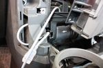
62 viewsCutout done, all that's left is to stuff the socket into the cutout
|
|
HOT!239 viewsthat is degrees
|
|
just crossed that18 views
|
|
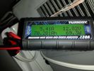
battery consumtion357 views24 hour power usage of an Engel 32L + NL 72L at 1c & -18c freezer in 80-92 degree heat in the shade. That's about 70amp hours.
|
|
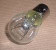
Land Rover Stop Tail Light dual filament bulb nominal 12 volt 21 / 5 watt filaments1427 viewsThis is the Land Rover part number 264590 dual filament bulb, (P21/5), that inserts into the upper two tail lamp receptacles. In the upper one, both filaments function, in the lower one, only the 5 watt tail light filament functions.
I regard it as not a good practice to routinely switch bulbs when the tail light filament, (5 watt), burns out on the lower bulb. The broken filament can jiggle over onto the brake light filament, (21 watt), and short the circuit to ground or something else not predicable.
There are also arguments to say that quality control is better on the Land Rover marketed bulbs than say far east sourced bulbs. Filament construction, and hence resistance can vary and mislead the current sensing circuits monitoring the signal light systems. Also when the bulbs are properly installed, all filaments should be standing vertically and not at any slope.
These are the sort of obscure circumstances that can lead to false trouble messages on the display, dropping to the stops, and subsequent concerns - all over a tail/signal light bulb.
For example, the filament life of both the tail light and the brake light filaments in the P21/5 bulb is significantly less than the USA common 1157 dual filament bulb, (1000/250 vs 5000/1200 hours); brightness in the P21/5 is a bit more, (3cp/35cp vs 3cp/32cp where cp is candle power), but current consumption is oddly less, (0.44a/1.86a vs 0.59a/2.10a where a is amps). It is the quest for efficiency vs maintenance trade off.
|
|
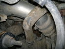
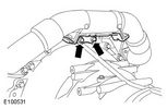
Charge Air Pipe - turbo end.101 viewsThe maint manual identifies releasing the pipe hose clip in the center of the photo. Pity who ever built this engine Put the hose in such a position that access to it was near impossible. I released the other clip at the turbo end of the flexi hose. Easy to get to but a right git to release the hose of the turbo.
|
|
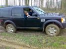
Well and truly stuck on a green lane at the weekend, there was a hill that does not show up in the photo!273 views
|
|

Engine Accessory Drive Description and Operation882 viewsThis 2 page pdf shows both belts for the 4.4L petrol V8; the primary serpentine belt, (the long one), and the shorter secondary that drives only the radiator cooling fan.
The various accessory pulleys the two belts are each associated with are numbered and an included table describes each.
When replacing belts and pulleys, count the number of grooves on both your old items and your new replacement parts. It has been known for an pulley with the wrong number of grooves to come with a replacement part or the replacement belt has the incorrect number of grooves; hence make certain the groove count on the new parts are the same as the removed items.
|
|
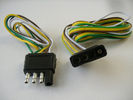
4 pin NAS flat connector from NAS small trailer382 viewsThe connector with the three exposed pins is the end that would commonly be located at the trailer hitch end, (front), of a small NAS lightweight trailer that has no electric brakes. This plug would connect into the flat 4 pin connector at the rear of the 3.
Note the order of the pin functions and wire colours: White is ground; the next pin is for tail/marker lights using the Brown wire; the Yellow conductor is for the left turn signal, and the far pin uses the Green conductor for the right turn signal.
There is no separate brake light conductor as NAS spec vehicles most often combine the brake and signal light functions to the same bulb filament rather separate filaments in different bulbs. The LR factory harness resolves that design difference.
Fortunately, the Land Rover NAS assembly pin order for the 4 pin flat plug maintains the above described conventions.
|
|

Air Distribution and Filtering Systems2084 viewsThis is 3 page pdf with coloured drawings of the air distribution ducting for the front air system.
Also included is a sketch of the pollen filter location within the front heater ducting. Note that two types of filters are available: a) the cheaper dust/pollen filter and b), the activated carbon filter that removes smells from the air. Installing the more expensive activated carbon filter means you never smell a cattle truck or chicken farm again. It really works.
|
|

Air Conditioner Specifications 4.4L V81570 viewsThis 2 page pdf is just the specifications for the AC system. The refrigerant type is R134A.
Note that when topping the system up, it can be a good idea to include some of that ultra violet light dye that will glow to show leaks and loose fitting.
|
|

Air Conditioning and Heater Control Components2425 viewsThis is a 21 page pdf that really explains how the air system is supposed to work. Discussed are the exterior ambient air sensor, where and how it operates; the interior temperature sensor as well as humidity sensor.
|
|

Alternator and Regulator Wiring Diagrams, TDV6 and petrol V8 and V61989 viewsThis is a three page pdf that shows the alternator and regulator wiring for the petrol V6, petrol V8 and TDV6. The pdf can be either printed or by right clicking on the displayed pdf, rotated as required for viewing.
Of interest is that the regulator gets its instructions primarily from the Engine Control Module (ECM) and only secondarily from the vehicles electrical buss. The conductor from the battery thru the 5 amp fuse F20E is to provide initial power to excite the alternator at startup and then secondarily, to instruct it if the PWM signals were not available. Primary instructions to and from the ECM are thru the two other conductors via a digital like Pulse Width Modulated (PWM) signal.
If F20E, the 5 amp engine compartment fuse box fuse is blown, the red alternator light on the dash will be illuminated. This means that the alternator could be OK, but if the F20E fuse is blown, no electricity will be generated. Hence check the F20E fuse if you get a red ALT light or some indication of the alternator not working.
Regarding operation of the red ALT light on the dash, it is not the regulator within the alternator that tells the red light to illuminate, or not, but instead the ECM. This is the reason the red light does not function in the same manner as with older vehicles. With the 3, sometimes you have illumination and sometimes not depending upon what the ECM is thinking. What this means is that you can have an alternator that is failing but the red light does not illuminate as the ECM is compensating for reduced alternator output - maybe by draining the battery and or cutting back on vehicle electrical loads such as shutting off or cycling the radio amplifier or heated seats.
|
|

Alarm System description and Operation1052 viewsThis 9 page pdf explains in detail how the anti-thief, (alarm), system is supposed to operate. The system uses the door ajar switches to provide alarm system signals; as such there are few separate contacts related to the alarm system only.
Page 6 of 9 is of particular interest as it describes the trigger log that is accessible with the dealer T4.
|
|
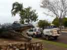
The Croc that ate Tata - Normanton134 views
|
|

60 viewsColdweathers, classic 90 blew up its expansion bottle, he was glad of the ride to the top but funnily enuf didnt want a tow to the bottom, some say it may have been due to the fact that his 90 looked like it had been taken jet sking on the back of a D3
|
|
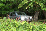
283 viewsCALENDAR 2011 ENTRY
This is in Puerto Rico. LR3 parked in the shade while we hang-out at a secluded beach that can only be accessed in 4x4.
|
|
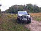
Ooops, found the mountain bike trail. KW Hydrocut16 viewswe were out one day and suddenly I seemed to recognize the power lines, and the fact that the mountain bike trail runs alongside the lines.
This is obviously a wide section of trail, but it's still the KW Hydrocut mountain bike trail.
|
|
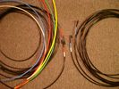
6mm PA12 grade nylon tubing with heat shrink applied 544 viewsShows some of the 6mm air line with heat shrink applied to one end of tubing. Shrink will be applied to the other end once field cut to length. These four tubes, each about 20 ft (6m) long, feed to the rear. Re the front air lines, (not shown), four additional lengths, each about 10 ft (3m) long, are required plus one more 3 metre length for compressor air. The 6mm tubing is a Nylon product specified as PA12. There is also a very similar Transport grade PA11 material, however it seems that PA12 is the more common Transport grade now in use. Also the applicable DIN standard seems to be both DIN 73378 and DIN 74324 for the nylon tubing. The working pressure of the 6mm tubing is about 27 Bar and bursting 82 Bar @ 20C. This is for the 1mm nominal wall thickness material, (4mm ID, 6mm OD).
|
|

Add A Circuit Littelfuse Data sheet2278 viewsThe switch connects to what Littelfuse brand calls an Add-A-Circuit model FMH200BP which is an adapter that plugs in place of a Mini fuse and then has space for two Mini fuses, (original and a second one). In this install, only the original 5 amp fuse was used - adapter was so as to route power from fuse box thru fuse, then rocker switch, and then back to fuse box.
Before you install the Add A Circuit for this application, take an ohm meter and trace out the circuit path of the four slots that fuses could insert into. The path is more complicated than one might first think. As such, the orientation of the fuse holder in the socket matters for this application - that is for a circuit diverter, rather than accessory adder.
|
|

Land Rover Aerial Fin images for both Glass and Metal Roof Disco3 / LR3864 viewsAs well as the two different fins, this pdf also shows the plastic blanking plate for glass roof vehicles where no fin is installed.
The glass roof fin is secured by two security screws from the top into a plastic frangible glue on gasket. The hope is that when struck, the fin will shear off and not crack the glass roof. Re the metal roof design, the fin is secured from underneath via two nuts.
The pdf also shows the various electrical bits related to the antennas. In the UK, the fin would house not only a cell phone antenna but the TV and satellite radio antenna electronics as well; in the States, the Sirius sat radio antenna and a G type cell phone antenna if the phone kit was installed would reside within the fin. The SAT NAV GPS antenna is located within the High Mount Brake Light plastic mounted to the upper rear hatch.
|
|

Fin cell phone aerial drawing190 viewsThe factory aerial for the factory NAV / GPS on my 2005 HSE is within the high mounted stop light lens at the top of the upper hatch door. I do not have the factory installed phone kit, and as such, do not have the fin installed; instead there is just a plastic blanking insert to fill the cell phone aerial wiring hole in the metal portion of the roof; hence this requirement for an "external" cell antenna. For those that do have the fin on their glass roof, the fin is screwed on to a glued on plastic gasket, (sort of), and not bolted thru as per the metal roof 3's.
|
|
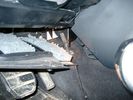
Air Conditioner Drain Hose on Drivers Side (LHD)2297 viewsThe corrugated rubber bit above and to the right of the gas pedal is the drain hose that goes down thru the carpet and floor sheet metal.
While it is bit hard to figure out from the jpg above, there is a rubber "strap" attached to the top of the corrugated hose that one uses to pull on to drag the hose up back around the black plastic heater "pan" drain. The same drain hose arrangement is on the other side as well.
One could I suppose run a plastic snap tie around the vertical pull strap if one was concerned about the hose slipping off again. See also the other jpg sketch which is from the Land Rover manual.
|
|
Air Conditioning Pipes (File 1)983 viewsIt\'s the smaller of the 2 pipes that is leaking. Both pipes are encased full length in the foam sleeve. You can see where the support bracket has \'crushed\' the sleeve. The bracket is what holed the small pipe. There is a bracket at each end and one in the middle. You need to remove the suspension reservoir to get to the centre bracket. Be aware that the bolts securing the brackets may be corroded and are likely to shear off on removal!
|
|
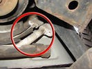
60 viewsOne bolt is visible at the front, but the other two are down the left hand side and best accessed by removing the small plastic guard behind the bumper. I also removed the small metal radiator guard between the bumper and the main sump guard (but that was mostly to retrieve the spanner I dropped!). The only issue with removing the plastic guard is the stupid plastic clips that hold it on may need to be replaced.
|
|
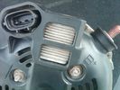
Alternator Plug and B+ terminal919 viewsPictured is the rear of the older Land Rover part # YLE500190 alternator showing the shiny cooling fin of the Regitar VRH2005-142 regulator under.
The first pin in the far left side of the connector is numbered #1 in the LR electrical wiring diagrams and is Battery Voltage Sensing (BVS); the middle pin, #2 receives a Pulse Width Modulated (PWM) signal from the Engine Control Module (ECM), and the right pin, #3 carries a PWM signal back to the ECM. Terminal Pin #2 on the LR wiring diagrams is called Alternator Control or ALT CON; Pin #3 per LR is called Alternator Monitoring or ALT MON.
Pin #1 is similar to what in older designs used to be called A or Batt, but is now called by Denso, S, AS, or Alternator Sensing for this design. Pin #1 also provides power to excite the alternator at startup until the PWM instructions over ride the battery voltage info. Land Rover calls the electronics under the pins a Smart Regulator, ironic, as it has to follow orders from the ECM rather than give the orders - new age thinking I guess. This is different from older design internal regulators that look at just the battery or the electrical buss voltage and then decides itself what to do.
It is almost like we are back to the external regulator designs of old, except that the ECM may decide that instead of telling the alternator to make more power, to load shed, and hence shut down the heated windscreen, seats, or whatever other electrical loads it decides are appropriate. My view is that the "smarts" are in the ECM and that the "regulator" should be regarded if not dumb, then as being a slave to the ECM.
|
|

how did that slip in here322 views
|
|

Thread upload8 viewsImage uploaded in new thread
|
|

That big!21 views
|
|
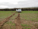
Muddy field162 viewsDid we just dig that?
|
|
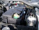
Aux Battery showing ground cable bolt "upside" down 1577 viewsIn order to obtain sufficient height clearance to get the plastic cover back on, I had to install the ground cable to the underside of the battery post connector.
Note the battery vent hose, (approx 5 ft required) is run down into where the windshield washer fluid container is located. There is not much electrical or metal in that area to be corroded by battery gas plus the open end of the vent hose tends to be protected from dirt and stays clean as well.
|
|
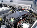
BCI Group 40R Deka 640RMF battery showing vent hose run forward to windshield washer reservoir area 1430 viewsRecessed post "Euro profile" battery to "match" OEM and stock Land Rover bracket; note that the Traxide SC80-LR module is mounted at an angle to allow for the main cable to sit under the cover so cover still closes.
The battery is a nominal 7", (180mm), high, but sits on a 1" battery spacer set under to raise the bottom front end of the battery such that the approx 11", (290 mm), length of the BCI 40R battery rises above the angled plastic nibs at the forward end bottom of the case front; hence sufficient space, (1/4", 5mm) remains at the brake reservoir end.
Also the 40R battery does not have hold down "flanges" on each end; on the sides yes, but not the ends so no additional length is required.
When I had to replace the 40R, this time I installed the shorter, (9.625"), taller, (7.5") Interstate BCI 47 / DIN H5 battery which eliminated the spacer on the bottom and better fit the stock LR tie down bolt lengths. Deka also has a BCI 47 / DIN H5 that would work fine as well.
|
|
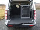
B24 TransK9 Dog Transit Box for Discovery 471 viewsThis box is designed specifically for the Discovery so that the 6th seat can also be used.
|
|
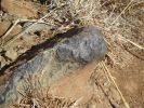
Bad Rock61 viewsbenign looking rock that punctured the sidewall of my new General Grabber AT2 (500km done on tyre)
|
|
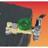
Battery Disconnect Wirthco 20308 Knob Top Post 890 viewsThis is a battery post style disconnect, usually for the negative terminal. There is a hole drilled in the round end off the battery so that flat terminal can be attached as well as the normal battery post terminal. I did not use this hookup arrangement, however I show it for information only.
|
|

Caterpillar Battery Size cross reference chart and battery profiles including post layout753 viewsThis pdf has a dimension, (metric and inches), cross reference chart plus another sheet that provides BCI and DIN cross reference numbers and shows post locations plus bottom ridge tie down locations, (or the lack of).
This data was for me, hard to find, and helps one in selecting a suitable physical size of Aux battery for the space available.
|
|
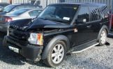
Bent Black Betty228 viewshard to believe that in this condition she\'s a write off, what got her was the cost of tricknology repairs, seatbelt pretensioners, airbags etc etc, & declining values, repair estimates €12500, value €13000. a no brainer really
Note TASTEFULL G4 sticker
|
|

Bin Cover removed showing forward release clips that clip into the two rectangular slots.10 viewsOne has to pull up on the Bin Cover to unlatch the two metal clips, hence why release of the C pillar cover makes the bin cover removal and reinstall easier.
|
|

Buzzer located under black plastic cover.12 viewsThe white electrical connector clicks into the buzzer housing that is shown protruding from under the black plastic cover. There is a little tab on the white plastic that has to be squeezed to release the connector. In other words, do not pull on the two conductors.
|
|

White plastic pin that has to be partly removed to assist in release of buzzer cover.11 viewsThe white coloured plastic pin is located near the C pillar and has to be partly pulled out to release the black plastic buzzer cover.
|
|

Bin cover removed to expose plastic moulding covering buzzer.10 viewsI guess this moulding is helping to retain the bin cover when in place rather than to "protect" the buzzer but that is also what it seems to do. In any case, unscrew the two large screws and lift moulding off exposing the buzzer.
|
|
Black Supercharged Badge100 viewsGreat tip drilling from the back and you won\\\'t damage the lip that the badge is recessed in
|
|
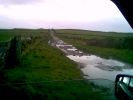
Black Lane, Mellor Moor171 viewsLooking at tread marks, appears to be only tractors that come up here of recent - until me!
|
|

crankshaft bolt24 viewsBolt on left is new one for upgraded oil pump casing. Bolt on right is what came out. Notice damaged end and shortness of bolt. Inside of crank was inspected wirh borescope and threads etc all ok. New bolt goes in and out ok. Few filings inside but otherwise clear. Not sure why old bolt ended up like that.
|
|
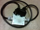
Box Closed with 7 Blade NAS connectors586 viewsBox closed up and ready for use. The box and cable connectors are reasonably weather tight and hence can be submerged for a bit while doing a creek crossing but as with the 3, do not use the creek bed as a parking stall. Similarly, the connector recessed into the bumper will probably remain somewhat dry as long as you keep moving but if you get stopped, well that is another story.
As such, I put a vial of desiccant in the metal box prior to closing it up to reduce corrosion due to moisture build up.
|
|

Brakes Description and Operation2231 viewsThis is a 17 page pdf that describes the operation of the various braking systems: the ABS, CBC, DSC, EBD, ETC, EBA, EDC, and HDC. Also discussed is the yaw rate and lateral acceleration sensor as well as the steering angle sensor.
|
|

Black Deposits to interior of Brake Light Switch2861 viewsThere are two contacts, one on each side of the vertical plunger under the copper metal. The set of normally open contacts on the left side that carries the power for the brake light filaments, (15 amp fuse F15P), is apparently not heavy enough as the contacts deteriorate and generate the black residue.
The set of normally closed contacts on the other side appear to be sized OK. There is not as much current, (5 amp fuse F66P), flowing thru the contacts to the ABS module, however the contacts are likely adversely affected by the black residue produced by the other deteriorating set of contacts.
One presumes/hopes that the newer replacement switch now has contacts heavy enough to carry the brake light power. It would be ideal if the ABS set of contacts were sealed from the brake light contacts to prevent contamination of the normally closed set of contacts.
|
|

Brake Light Switch, Find, Remove, and Install Instructions 7853 viewsThis is a two page doc outlining where to find the brake light switch, how to remove it, and then install the new one.
Note, do not move the brake pedal when removing or installing the switch. Let the brake pedal hang where it wants to. The switch design is actually cunning, and as such is supposed to make the removal and install fool proof. Hence if you think too much about it, you can wreck the new switch.
If you want to inspect the interior of the switch, wait until you have removed the old switch. You can then just unsnap the blue from the white to get it apart. Inside, the switch is quite simple, (no circuit boards), but it will probably show black dust from failing contacts.
I think the reason the switch fails is that the Normally Open, (NO), contacts of the brake light contacts were made too light to carry the current load for make and break of the tail light filaments. I also think the black dust created then fouls the Normally Closed, (NC), second set of contacts for the ABS circuit. As such, the Normally Closed contacts become intermittent in operation and display as a fluctuating open and closed circuit condition to the ABS system when the ABS should be seeing a steady closed circuit. Hopefully the replacement switch contacts are more robust and may be as I recently replaced my switch again just as a matter of maintenance. While in a redesign, ideally the NC contacts should be sealed or at least separated from the NO contacts, when I inspected the removed switch, this time there was no black dust present.
Probably the removed switch will have a Land Rover oval logo moulded into it, the new one, FOMOCO.
|
|
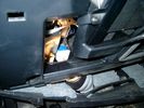
Brake Switch Visible thru Opening4975 viewsThe blue and white bit is the switch; the sort of gold appearing box,(it is really black), you will not see in your 3 as it is a Smooth Talker brand amplifier for my Blackberry phone antenna. This install is detailed in the SmoothTalker phone antenna section of my gallery.
One way to remove and install the switch is to lower the "horizontal" panel above the brake pedal as shown where the flashlight head is located. To actually remove the switch, you slide your hand thru the gap and rotate the switch clockwise 1/4 turn while watching thru the rectangular opening. Installation of the new switch is the reverse of above - 1/4 turn counterclockwise.
Before you remove the switch, note its orientation - horizontal with electrical wires to the left. That is the way it should look after replacement as well.
The second time I replaced the switch, I did it all thru the rectangular opening and did not remove the horizontal panel - that is experience helping out.
The knee kick you have to remove regardless. It is sort of hinged at the bottom so you just pull at the top and sort of rotate the knee panel and then pull upwards for two plastic "fingers" to clear the slots they reside in.
|
|
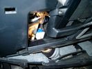
Smooth Talker Amplifier Box mounted below near steering column.179 viewsThe gold look box due to the lighting, (actually black), is the antenna amplifier located near the steering column. It can be put anyway but this seemed an OK location as I ran the antenna connector cable rearward from here to the back corner of the 3 and then up to the underside of the roof glass at the rear. The blue/white thing is the brake light switch that often must be replaced. See the Brake Light Switch file within this Gallery regarding the switch replacement.
|
|

Black Deposits on Brake Light Switch Plunger2758 viewsThis jpg I got off another forum and is typical of what one will see when one opens up the removed brake light switch. The black powder is residue from arcing of one of the pair of contacts within.
Hopefully the newer switches with the FOMOCO logo moulded into the plastic are improved from the Land Rover logo marked early units, however I doubt it.
The Ford part number is SW-6572 and/or 7E5Z-13480-A as used on the 2006 to 2009 Ford Fusion's and Mercury Milan's; the Land Rover part number is XKB500110. Cost of switch could be about twenty five dollars. A previous LR part number for the switch was XKB500030, so hopefully the newer LR part number, XKB500110, reflects some improvement in reliability.
It is possible that the new switches are better as I installed a replacement 72,000 km, (45,000 miles) later, at 195,000 km (121,000 miles). When I took the removed switch apart to inspect, it was clean inside. There was no black dust - the switch looked like new, hence they must be improved now.
|
|
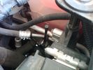
Vertical Breather Hose before cutting off OEM cap.1778 viewsThis shows the plastic vertical breather tubing and OEM cap prior to being cut off. The tubing is located on the driver side at the front near the radiator. One cuts about 3/4" to 1" off from the top. The TSB says 20mm.
I tried blowing thru the cut off piece and was not very successful. The cap seemed plugged. I am beginning to think that there was a very good reason for Land Rovers's Technical Service Bulletin, (TSB).
|
|
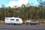
Disco and Boroma with Hyland hitch fitted inverted.153 viewsNote that it is now absolutely level.
|
|

Central Door Locking Operation Description1458 viewsThis 17 page pdf explains how the door locks are supposed to operate. Note that on page 9/17, the explanation of the operation of the hood ajar switch is wrong. It operates similar to the door and tailgate ajar switches; that is when a "door" is closed, the switch is closed to maintain a ground back to the CJB. Opening the hood, door, or tailgate removes the ground breaking the circuit and hence allows for an alarm condition.
|
|
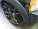
Snow Chains Installed - Land Rover LR3HSE94 viewsSnow Chains that seem to fit a Land Rover LR3HSE
|
|
This show that the angel of the radio body is diffrent from the original, hence shall some plasic be removed - I used a dremmel and removed 7 mm of the horizontal bar inside 160 views
|
|
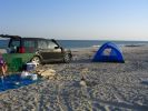
Campsite on Mazirah208 viewsA fabulous deserted sandy beach that runs for miles on the east coast of Mazirah Island, off the Omani mainland , views across the Arabian Gulf, and turtles and hatched terrapins.
|
|
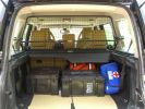
Load space368 viewsShows the SA Front Runner Wolfpack stacking plastic storage boxes that I keep laod straps etc in and the 2nd is tool kit, spare belts, jerry can funnel and tools, plus airline and tyre inflator/deflaotr for ARB on-board compressor, HD jump leads. ARB Winch pack (Orange)with strops, snatch blocks, shackles, gloves, and 2 ARB recovery dampers. Really great 4x4 1st Aid kit from Outdoors warehouse in SA. LRs own loadspace guard - not the best design if you want to store a long load. Mods to be carried out!
|
|
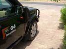
2009 MY?239 viewsThe wheelarches, door sills, and door mirror bodies have all been sprayed to match the body colour. Same as 2009 MY? I think this looks really good, and is so much easier to keep clean than the textured plastic that suffered badly out here from dust/dirt ingraining and UV discolouration.
|
|
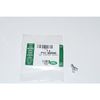
Clip Spring Metal FYC 500040 that holds LR together1747 viewsThe jpg is of the spring metal clip, Land Rover part number FYC 500040 that holds most of our 3 together - well at least most the interior trim parts.
If you are going to remove interior panels, you may as well stock up on a few for replacement as upon panel removal, the clips tend to spring away into deep never to be found voids within your 3.
|
|
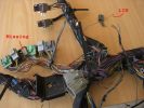
example problems113 viewsInspection showed another Cut Airbag connector, a Missing connector and a few rogue wires at the bottom, the silver one marked Lin, is for the LIN BUS and is supposed to be like that though
|
|

Thread upload14 viewsImage uploaded in new thread
|
|

Thread upload12 viewsImage uploaded in new thread
|
|

Controller 2132 viewsI find that the controller is easier to use when angled forward
|
|

Cooling system hoses - 4.4L petrol V81109 viewsThese are the cooling system hoses on the 4.4L petrol V8. The little odd shaped bleeder hose, (LR006158), shown in the top right hand corner can give problems. There is a plastic tee with a threaded air bleeder outlet located in the middle of the hose. The plastic tee can or will fail due to I guess heat distress.
A BIC pen can serve as a field fix, however for your parts kit, a nominal 3/8" ID hose size brass hose barb inline connector plus a couple of hose clamps is suggested. Better yet is a threaded hose barb brass coupling or a tee and bleeder valve to allow bleeding of the line. Land Rover now makes the plastic bleeder valve that breaks available as a separate part, # LR027661, where 0 is a zero. As such, one can now purchase that part only for addition to your field fix parts kit.
|
|
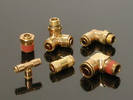
Detroit Fluid DOT air line fittings718 viewsThe picture shows the internal ferrule that is characteristic of the DOT / TUV accepted fittings for highway vehicles. Most often these fittings are metal however the Land Rover John Guest 6mm straight connector is all plastic and has the internal ferrule.
|
|

ng on the drive after a legacy of 7 silver Discos478 viewsI\'ve had silver Discos so many times now the neighbours thought that this was a loaner
|
|
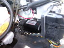
CounterAct Power Supply mounted 247 viewsPicture is blurred, however power supply is 3M two sided tape to the flat black plastic of the second battery compartment just under the antilock brake pipes to the fender side of the brake fluid reservoir. The white wire to the left rear coupler pad runs thru the firewall hole near the steering column. The blue wire to the right front coupler runs across and above the engine following the other wiring looms that cross the vehicle.
|
|
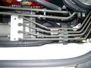
CounterAct Power supply mounted under brake lines.194 viewsThis top view shows where I located the power supply. It is attached with 3M sticky to the black plastic surface that is located under the brake lines.
When the system is operating properly, the red LED pulses about twice per second.
Some users claim they can hear a very slight hum or whine coming from the unit. My unit seems silent.
|
|
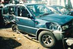
The car that we hit, pushed the back axle about 2\' through the car!288 views
|
|

C pillar cover removed to facilitate removal of bin cover.9 viewsNote the "ribbon" behind the top left corner of the C pillar cover. This is something to do with the curtain air bags, hence do not mess with it. I dislodged the cover to make it easier to pull up and extract the black plastic bin moulding. It is not necessary to totally remove it and would be what I call a big deal - seat belt, air vent and ducting as well as that curtain concern.
|
|
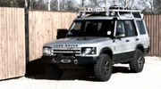
D229 viewsMy Discovery 2 in its heyday. I really loved that car!
|
|

who keeps parking that jap thing in the way?43 views
|
|

thats a better effort G O52 views
|
|

Steering wheel audio controls and iPod dock103 viewsFitted an iPod dock and steering wheel audio controls. Got then both from Nick at Yeoval Landrover in the UK at a fraction of the price that the Aussie dealer wanted.
|
|
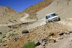
453 viewsMore photos coming soon. 7000 km with NO problem. Only took a 6th spare wheel, a tool box, air compressor, window shades. What a great Disco !
PS: note that my disco has manualy inflatable air sping in addition of the standar terrain response.
|
|
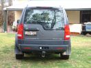
D3 Mudflaps (That work and don\'t break)265 views
|
|
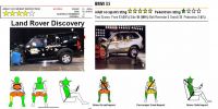
D3 vs X5 in NCAP crash test412 views Looks that D3 was as close as it can be to get 5 stars but falled JUST below the 5 star limit.
|
|
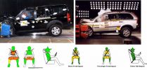
D3 vs. XC90 in NCAP test416 views Actually D3 has more green color for the passanger as XC90 (that got 5 star marking). So if you really love your wife, D3 is safer to her in case that you are driving and she is a passanger :=)
|
|
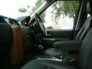
Interior124 viewsThat wood trim is going - to be replaced by piano black before I pick it up
|
|
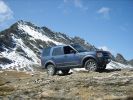
D3 High Alpine Pass450 viewsCALENDAR ENTRY
Sept.08 on the way back from Monaco towards Switzerland. The \'Col de L\'Iseran\' is the 3rd highest road in Europe and this shot is taken slightly higher than that!
|
|
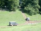
119 viewsD3matt's first go up that innocuous looking slope...
|
|
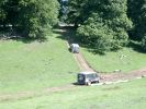
106 viewsD3matt's first go up that innocuous looking slope...(continued)
|
|
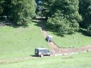
94 viewsD3matt's second go up that innocuous looking slope...
|
|

92 viewsD3matt's xxx go up that innocuous looking slope...!!!
is that Rob yawning?
|
|

Thread upload0 viewsImage uploaded in new thread
|
|
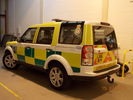
D4 Being Prepped for LAS26 viewsThis is a Disco 4 (unknown spec) being prepped up at my workplace for the LAS, having new comms kit put in and stuff. What you can't see from this angle is that the front grille and headlights have been taken out.
|
|

Disco3 on the move in Dangalli Conservation Park - at speed (south of Yunta)178 viewsMusic heard in video is from the stero blasting away inside the Disco - and yes...that was a cattle grid being crossed at the start :-)
|
|

Thread upload20 viewsImage uploaded in new thread
|
|

Deka Battery Dimension Data615 viewsThe battery size that I installed for my auxiliary was a BCI 40R battery as it was for me the easiest to fit and was also a cranking battery. The case profile was such that no tie down fins were located on either bottom end, (sides yes), and length wise, it was only about 11" (290 mm) long. As such, I did not have to grind the nibs at the front bottom of the plastic surround.
I did however raise the bottom of the battery above the angled nibs as I set the battery on a 1" (25mm) high plastic spacer. The total height, (battery plus spacer), was about 8" (200mm) so the battery top still fit under the Land Rover factory cover.
For the Aux battery, when I replaced the 40R, I installed an Interstate BCI 47 which is similar in size to a DIN H5. I was therefore able to eliminate the vertical spacer as the Group 47/H5 is the same height as the DIN H7/H8 stock LR spec starting battery. As such, the standard battery tie down bolts can be used without modification. The Group 47 battery is 9 11/16" long x 6 7/8" wide x 7 1/2" (190mm) high.
|
|

Cooling System - Description and Operation 4.0L and 4.4L petrol engines 5 pages1028 viewsThis is a 5 page pdf that provides some insight into how the coolant flows thru all the hoses. Of interest is the paragraph,(page 3/5), that attempts to explain how and why the thermostat is designed to open at different engine operating temperatures - in brief, the reason for the spaghetti tangle of small hoses on the top of the engine.
There is also reference to an engine oil cooler that I gather cools something I think related to a supercharger, if fitted.
|
|

415-07 Video Information724 viewsThis is a 5 page pdf that explains the operation of the overhead DVD setup as well as the TV option.
|
|
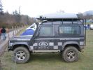
extreme medics rapid response 90222 viewsdoesnt come any guccier than that !!
|
|
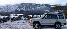
My D2 above Loch Ness at a winter Highland 4WD Club Trial, c. 2003.104 viewsThe drive there made me realise that even in a Disco road tyres are lethal on ice..
|
|
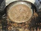
Roamingman decides that he wants some of the Scottish countryside 110 views
|
|
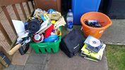
Stuff that came out of the Disco30 views
|
|
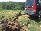
LR3 to plow your garden298 viewsI found this jpg where a current LR owner is using his LR3 for a similar purpose as the original Series units were designed to do - that is serve as a tractor for plowing a field or I suppose a garden.
In this case, I note the hitch is one of those that attach to the factory tow loop, (Rhino Hitch), rather than the factory product that inserts from the bottom and hangs down - (like a plow), but all the time. One of the other jpg's in this album shows the two factory variations plus a third jpg shows a closeup of the Rhino Hitch.
|
|
Pull cord as a backup63 viewsI added a pull cord so I would not kept caught with a broken release on the tailgate again. Think about a flat tyre if that happens to you.
|
|
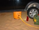
Spread the laod133 viewsEncouraged that the load on the jack still doesn\'t cause any sink in, even in soft sand, with most of the weight of the car on it due to the side slope.
|
|
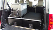
Ironman Drawers and Fridge Slide112 viewsI hate kitsets, over 100 bolts to assemble this unit and lost gallons of sweat, must have read the instructions a hundred times or more but final product does not look so bad. A few bolts hanging out the sides of both slide and drawers that may catch things so time will tell if I made the correct purchase.
Maybe one day I will make some side wings to cover the sides properly.
|
|
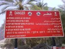
good to know that \'drowning accidents are now popular\' - signpost near the pool139 views
|
|

That's why they're called Ridgebacks347 views
|
|
What\'s that pigeon been eating?323 views
|
|
72 viewsTested with the multi-meter, fridge and air mattress pump. All of them were as surprised as me that it worked!
|
|
D+P Display in Temporary Position - look at that dust!488 views
|
|
Screen profile437 viewsNote that the passnger airbag is switched off when the screen is fitted - no problems to date with solar gain on the rear of the screen
|
|
Solo screen mount490 viewsNote that the mounting bracket doubles as a screen mask
Mount is Manfrotto \'super clamp\' & arm
|
|
Now that a nice veiw55 views
|
|
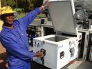
Fridge pulled out & open ( thats my mate, Caiphus)221 views
|
|
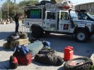
Babu - great guy from Mozambique who joined Kingsley\'s core team.158 views"How the heck am I gonna fit all that in there?!"
Packing all the kit in Ondangwa. Amazing what you can get into a Defender!
|
|
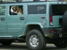
That Hummer driver is a dog75 views
|
|
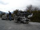
Destroyed D3156 viewsAll that is left of a D3 after plunging down the Verdun Gorge in the South of France.
|
|
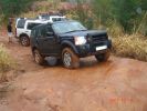
The "alternative route"161 viewsThis was the start of the rocky bit that cut out the snotty slopes. Wasn\'t the way to go unless you quit
|
|
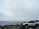
disco at finore76 viewsfound a little patch that strayed from the main road near finore, co clare.
|
|

86 viewsLHS rear wheel well, with inner guard off. The rear AC lines (assuming you have an HSE) don\'t run in same way as the RHS, so on all cars, you can fold the red line inboard, with the bend roughly at the blue line, so that the very rare contact with larger tyres is eliminated.
|
|
Look at the articulation on that!234 views
|
|
Used the wire connector that came with the timer - no probs!69 views
|
|
The obstacle on jockstrap that caught us for a while.89 views
|
|
229 views
|
|
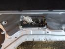
An alternative approach132 viewsDue to low temperature, and the size/mobility of my hands I decided that the easiest way to open the tail gate was to destroy the old Bowden cable and then pull centre core to release the tailgate - it worked, and doing this earlier would have saved a few cuts and grazes.
|
|
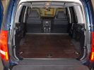
D3 Commercialisation622 viewsThis is the pic that was sent to me by the dealer to show what would be done to turn my SE into a van. (The car shown isnt mine)
|
|
Hmmm, so that\'s what keeps it up?60 views
|
|
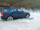
All that salt will do wonders for the chassis!446 views
|
|
V8 HSE Auto Reg 734 EAB367 viewsThis is the model D3 that everyone's got.
Ever noticed that although its a V8 auto, it's got a clutch pedal??
|
|
36.5mpg for 184 miles - and thats on AT2\'s363 views
|
|
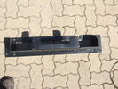
Top view of "Uncle Ray" discrete winch tray, after painting.106 viewsNote that towards the upper right there is a notch in the tray. This is needed for the specific winch's electric solenoid. The winch is a Mile Marker 12,000 lb hydraulic unit.
|
|
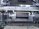
Close-up front view of partially-installed winch121 viewsNote that the sheet-metal flange just above the winch had to be notched to allow winch controller to be actuated. Also this same bracket had to be bent upwards to allow the winch hydraulic:electic solenoid to fit without rubbing. The nut on the upper-left bolt (the one with a very faint circle around it) stripped on re-installation, so the tray and winch pulling load is held only by the threads on 7 bolts....
|
|
Detail of hydraulic hoses attached to power steering hoses155 viewsHoses are attached to the upstream side of power steering rack. When winch not running, PS rack sees full pressure (ie, no change from design). Biggest challenge is running stiff hoses so that they align with attach points. I got Qantas employee who repairs hydraulic baggage loaders to braise in fittings (very tight spaces and tough access).
|
|
it felt much steeper that this!!203 views
|
|
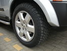
General AT 19"226 viewsget that tread!
|
|
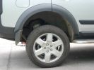
Suspension on extended mode266 viewsJust look at that ground clearence!
|
|
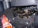
Mounting a non-LR fire extinguisher535 viewsShowing the plastic cover removed. I will make up a metal plate or bar so that the extinguisher frame can be mounted directly to this framework under the seat.
|
|
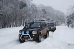
Mt Skene, Victoria, Australia - leading 2 D2s up the hill...196 viewsA great snow season in 2008. The Mt Skene road is one of the few alpine roads that is left accessible, but uncleared, so we can go and play!
|
|
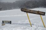
189 viewsMt Skene - 3 hours NE from Melbourne, Victoria. One of the few accessible but mostly snow-blocked alpine roads in Victoria\'s "high" country, that doesn\'t lead to a resort (and get cleared).
|
|
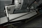
fits on exsisting holes that are already there,realy easy to fit182 views
|
|
182 viewsAnother shot of the right slider. The center support channel has drainage channels welded in that match the locations of the drain holes on the sill frame.
|
|
264 viewslook for the light shining through ...thats were the gromet is
|
|
260 viewslook for the light shining through ...thats were the gromet is
|
|
The swinging lump of iron that sit under the back,871 viewsLook how close it is to the wiring!
|
|
Exhaust Crossover Pipe157 viewsThis is the pipe that i am looking for.
|
|
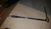
Thread upload18 viewsThis is how you reach that TOP BOLT holding your air compressor bracket on. 10" extension, swivel, and 10mm socket taped so it won't fall off while your feeding it through the air compressor maze.
|
|
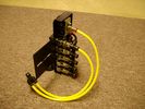
FASKIT on end view 864 viewsEnd and rear view of the FASKIT. Yellow lines are as shipped for hooking to the air supply; one line to valve/filler and other is to gauge. I will modify the arrangement to delete one of the yellow lines such that gauge line plugs into where the second yellow line is right now,(will be only one yellow tube), and then the air source line will plug into the port controlled by the valve, (hidden in this view but visible in other view). When white valve is in the ON position, gauge will read air source pressure, and be available to supply air to any of the selected four air springs. When valve is closed, the gauge will show individual air pressure in each of the air springs when a jumper is run between the gauge Schrader valve and the appropriate air spring Schrader valve.
|
|
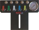
FASKIT air panel unmounted843 viewsThis is the manual air valve panel that is mounted in the "empty" space where the FBH normally resides. The gauge reads to a maximum of 25 Bar. The air tank relief valve is set just over 16.5 Bar (240 psig); the front air springs run maybe 9 Bar, (130 psig) and the rear, somewhat less, perhaps between 5 and 8 Bar. (70 to 115 psig). Max theoretical air spring pressure at full compression due to a big bump and full gross is approximately 27 Bar (390 psig).
|
|

G4 wading down the high street203 viewsTaken by a passer-by as I was enroute to an emergency - just luck that I found the shots.
|
|

Fluid, Filter/Pan Combo removal and install5980 viewsThese are the LR instructions re removal and install of the plastic pan/filter combo for the ZF 6HP26X transmission on the 4.4L petrol V8 LR3.
The instructions tend to ignore the reason you have to lift the right hand side of the engine about 40 mm. This is because of a frame cross member that interferes with dropping down of the plastic pan. The real problem is a vertical "oil filter spout" that rises out of the filter/pan combo up into the transmission. The spout is the suction pipe for filtered transmission oil back up into the tranny.
On the metal pan versions, the filter is separate from the pan, hence the filter remains with the tranny when the metal pan is dropped. The filter is then removed or installed independent of the metal pan, hence with the metal pan, there is no need to lift the engine.
If one is removing the plastic pan so as to install the metal pan, then some do not lift the engine but just drop the plastic pan enough to gain access to saw off the vertical plastic spout - it is a one time procedure.
Be aware however that the metal pan uses a flat gasket and the plastic pan uses a O ring like perimeter gasket that sits in a half round groove in the tranny casing. Also the metal pan uses 21 shorter torx M6x22.5 metric cap screws for the perimeter bolts. The plastic pan uses longer M6x28.5 torx metric cap screws.
|
|

Wiring Diagram Fog Lamps76 viewsR130 is the (R5 relay under the hood) The wire is blue grey that is hot when the high beams are on and opens the relay contact that turns off power to the fog lamps. North America Only
|
|

Thread upload6 viewsImage uploaded in thread 159579
|
|

Ford Sounder 4L1Z-15K864 A that I installed.12 viewsThis is the Ford sounder, part number 4L1Z-15K864 that I purchased and installed in lieu of the official Land Rover sounder. Note the part number is what is printed on the box (and also my invoice) but the part number on the sounder body is a bit different. I think a new box/invoice related part number is created each time the price of a part is changed. Regardless the Ford sounder was about half the cost of the Land Rover part and sounds the same as the removed factory buzzer.
|
|
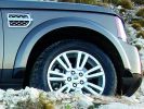
Split 7 Spoke on 2010 Discovery 472 viewsI noted that the tyre image has been flipped but the LR badging on the air intake is right way around. Interesting
|
|
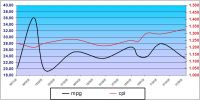
MS Excel chart of fuel usage in TDV6 first 3 months of ownership201 viewsReason for distortion at beginning is not known - average so far is 11.55l/100k (25.09mpg) for the 6 199k travelled. The fuel usage 'bumps' correspond with the city driving although they did mirror the cost for a while! A copy of the spreadsheet (105kb) that shows MPG and l/100k (but not miles) is available for the asking - just PM me.
|
|
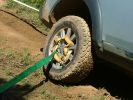
Traction127 viewsAll that held the D3 from certain death was about 25% of the tread width of a Grabber.
|
|
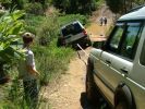
Insane117 viewsThis was the predicament that resulted in the panic recovery attempt.
|
|

Thread upload10 viewsImage uploaded in thread 191449
|
|

Series LR at Oil Sands Plant in Northern Canada circa 1968747 viewsThis is an end of shift picture taken about 1968 at the Great Canadian Oil Sands (GCOS) plant while under construction in the Ft McMurray area of Northern Canada.
I was surprised to see the yellow coloured Series single cab hardtop pickup parked in about the centre of the picture. I would say it is one of the few on site as most vehicles were Chevrolet's, (as are the other three trucks elsewhere in the view). The yellow painted vehicles including the Land Rover are most likely Bechtel owned - not leased - yes, that long ago now.
|
|

Fix stiff gear selector or jumping out of drive into neutral32 viewsThis is a document culled from a topic about a simple fix to teh gearbox selector lever that fixes a problem with jumping out of drive into neutral.
I made the document to give to my local independent and thought it might be useful for others.
Thanks to disco_mikey, EdF and Robbie from the original post whose information and photos made this possible (I take no credit for anything here apart from errors).
|
|

Fix stiff gear selector or jumping out of drive into neutral17 viewsUpdated 19 Dec 2012
This is a document culled from a topic about a simple fix to the gearbox selector lever that fixes a problem with jumping out of drive into neutral.
I made the document to give to my local independent and thought it might be useful for others.
Thanks to disco_mikey, EdF and Robbie from the original post whose information and photos made this possible (I take no credit for anything here apart from errors).
Updated after I did this fix on my own car.
|
|

Gore Tex data sheet on Breather Cap.784 viewsThis is a Gore data sheet on the air vent material that is within the breather cap. The filter material has both hydrophobic and oleophobic properties. That means it keeps water out and the differential oil in.
Also the membrane material is air permeable; that means air pressure is equalized between the interior of the differential and outside air. This is important when the 3 is flying at altitude in the back of a Hercules with the rear door open - that is the rear hatch of the Herc.
|
|

Gore Tex Oleophobic Membrane Vents82 viewsThese is a link to a Gore website that explains how the Gore Tex material within the breather cap allow pressure to escape (but retains the oil) and allows moisture free air to come back in but excludes free water.
|
|

Snake Lake136 viewsNo problem getting through this wash on our 2nd try. Tried to straddle rocks on first, that was a bad idea.
|
|
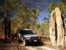
D3 in Kakadu National Park, on the track into Graveside Gorge51 viewsKakadu National Park is in a World Heritage area, with the entrance about 3 hours out of Darwin. It took another hour to get to the un-marked track into Graveside Gorge, which then took three hours to travel the 41km in. Not a tough track, but a series of big wash-outs with very deep and soft sand in the creek beds made driving fun. The most amazing thing, was that we had the whole place to ourselves. No marked tracks, so bushwalking involved blazing a trail using GPS and topo maps to find the way.
|
|
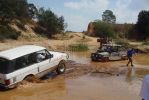
Heine Recovering me, and then I recover him. Really Sticky that day ;-)117 views
|
|
Suv that hates normal 4x4\'s207 views
|
|
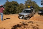
Testing that sump plate!113 views
|
|
Rhino Tow Loop Hitch270 viewsThis is a receiver end view of the Rhino Hitch that ties to the factory tow loop. In addition to improved strength, it does not reduce ground clearance as does the factory style when installed.
Land Rover in early advertising videos when the 3 first came out showed the D3 hanging from a crane via the frame. The intent was to show how strong the frame is and by inference, the rear tow loop, specifically noted as being good for 6 tonne. The video ends before anything dropped or was lowered back to the ground, so one of course does not know for certain. The Rhino Hitch design however picks up on the apparent evidence of strength and certainly the additional clearance.
|
|
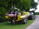
Now Thats What I Call A Rib46 viewsSpot the old P38 towing my baby. Sorry its an old photo.
|
|
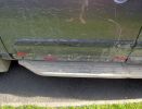
Woops, where has that piece of trim gone?135 views
|
|
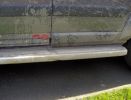
Hmmm, that dent wasn't there when I started.137 views
|
|
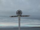
"The Icon". The man in the hut that does your sign ,, had gone home ..155 views
|
|
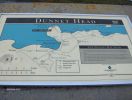
......... So, then I found out that in fact Dunnet Head is the top most point of the UK. Had to go ..148 views
|
|
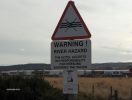
Sure that wasn't there in front of me when I parked up last night ????156 views
|
|

Thread upload198 viewsImage uploaded in thread 162283
|
|

The on/off switch for the middle outlet10 viewsThe left switch without the label is the one that now controls the middle 12V outlet on the second row. It used to be the power on/off of the car-computer.
|
|
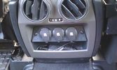
12V outlets for the 2nd row13 viewsI used a part of the old front (which was broke) to cut out a 'mount' for three 12V outlets for the second row.
The outer outlets are switched on whenever the ignition is on as I used the connector that originally was out there.
The middle outlet is connected to the auxiliary battery and is switched on/off through a rocker switch in the central console. (other picture)
This middle one is going to be used for our small fridge that usually resides just there when we're on holiday.
|
|
The on/off switches of the multimedia headrests17 viewsThese switches were installed to power on/off the previously installed gamecube and the screens attached to it.
When I removed the gamecube and lately the screens as well, I was clever enough (surprised as well) to leave the switches and all the wiring that I had running around.
They came in handy when I installed the multimedia headrests and are now adding an extra power on/off control of the screens.
|
|
The on/off switch for the battery display22 viewsThe right inner switch 'powers' the auxiliary battery display. I might use that one to power on/off the driving camera (which will be arriving soon) as well. Although I'm not sure yet.
|
|

64 viewsAdded a lead coming from the 12V outlet in the front console. That one is activated only when the ignition is set to I. So that's actually what is referred to as accessories in the manual of the radio. The OEM connector for the head unit did not have any similar lead. The yellow is permanent 12V, the red (on the converting OEM 2 ISO) is the accessories 12V.
|
|
38 viewsWhen adding two single DIN supports together, you get quite a gap at the front.
This gap was way too much in my case, as it turned out that both supports started to bend when putting them both in the facia. Not that good, so I decided to cut off the upper part of the lower DIN support.
|
|

secret shrine21 viewslocated in a secret place tgis old shrine is all that remains of an old buddist temple
|
|

Hilux that collided with Disco3227 views
|
|

LOOOOOK atthat MPG!!!92 views
|
|

The rock that saved Stu s arse120 views
|
|

Puzzle - how do I get to that cat on the other side?52 views
|
|
End of the line at Ras Al Khaimar72 viewsI am led to believe that this example was left overnight on the beach broken down - by morning the natives had stripped every last piece of usefull equipment out of it, engine and all and dragged it across the creek back to their village
|
|

nice view from the top but its getting there that counts25 views
|
|
Harness location15 viewsArea of harness that chafes against battery terminal
|
|
trim that fell off30 views
|
|

LP scoped 222 viewsBy connecting a Low Amps probe to the fuel pump's voltage supply wire, you can view the pump's current waveform on a digital storage oscilloscope (DSO). The scope pattern will reveal internal wear in the brushes and commutator that may not show up in a traditional pressure or volume test.
Observing the waveform will show if the pump's amp draw is normal for the application or is high or low, and if the pump is operating at normal speed or is running slow. Problems such as a bad spot on a commutator or a short or open in the armature also will be obvious in the waveform.
A "good" electric fuel pump waveform will generally seesaw back and forth with relative consistency and minimal variation between the highs and lows. A "bad" waveform will show large or irregular drops in the pattern, with large differences between the highs and lows.
|
|
Oops16 viewsThat's why it stopped moving forwards and started moving down!
|
|
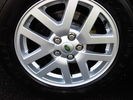
Wheels79 viewsAll 4 wheels in good order - would say "Perfect" but one of the 4 has an absolute minor scratch to it - which I had not noticed until I inspected them prior to sale. That minor not previously noted. Not bothered to take full size spare off to look at it, but as far as I am aware also in perfect condition.
|
|
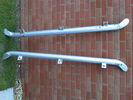
bottom of the side bars - they are 100% straight, just that dent on the bottom of one.132 views
|
|
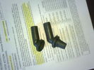
old and new elbows24 viewscomparison of elbows (left is the one that was deteriorated)
|
|

964 viewsRipping off the cheap carpet reveales the galvanised steel box with sharp edges that has been fixed in with 4 ton of silicon.
|
|

901 viewsripping out the tackky metal box that is part of the Irish commercial conversion
|
|

Windy79 viewsPepper showing that it was windy on the Cairn
|
|
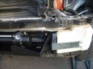
1681 viewsBracket that holds the washer bottel in now that the bumper has gone.
|
|
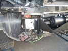
1720 viewsBracket that holds the pump that used to be attached to the bumper, Also it holds the winch solinoid pack.
|
|
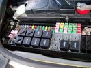
Picture of the engine compartment fuse panel5780 viewsEngine compartment fuse panel located near the battery. This is where F3E, (5 amp), F26E, (20 amp), Fuseable link 10E, (60 amp) and Relay 7E, the now upgraded 70 amp air compressor motor relay, part number YWB500220, (E is for Engine compartment fuse box), are all located. Fuse F35P, (5 amp), is inside the Passenger compartment behind the lower glove box door.
To keep the suspension from going down to the stops when driving, (or parked), it appears that it is only really necessary to remove F26E to depower the exhaust valve and generally keep all the valve block solenoid valves in a closed position trapping whatever air is within the air springs. F3E gets its power thru F26E, so when F26E is removed, the F3E circuit is automatically de-powered. F35P is more interesting in that battery power goes thru the ignition switch and F35P and then into the air suspension control unit. Apparently however, if F26E is removed, removing the F35P is not needed even when the engine is running.
With all fuses still in, if you have a problem, in practice, ideally, the compressor still works and will raise the 3 to an appropriate height. If so, one can then shut the engine off and allow the computers to go to sleep and then you remove the fuse(s). In actual practice, it seems that one need only pull the F26E fuse and can do so with the engine running. All the same, one might consider that the 3 is first a mobile computer, and secondly a 4x4. Computers prefer to go to sleep before the plug is pulled on them, however given that F26E circuit is always alive, then the computer never sleeps. With the fuse(s) pulled, and if you are still up, you can now be a 4x4 instead of a low rider. The whole purpose of the fuse pulling exercise is to depower the one and only system exhaust valve that is physically located within the compressor unit, (to keep it from opening), and secondarily to keep closed the four air spring solenoids within the block valves. This also shuts the air compressor down and stops the air compressor from making air even if the compressor is still good. That is why you initially need the fuse(s) in to allow the compressor to make air if it can.
|
|

Switch is blue colour thing thru the rectangular opening.3177 viewsThe blue coloured plastic bit thru the rectangular opening is the brake light switch. The fist time, I found it easier remove the switch by dropping the horizontal plastic panel, (two screws), and then slipping my hand in and rotating the switch clockwise 1/4 turn. The second time, I was able to remove the switch thru the rectangular opening and did not need to remove the horizontal lower panel. Obviously, I had to remove the sloping knee pad panel, (note sort of hinged at the bottom so pull back from the top.)
Regardless, do not touch the brake pedal - just let it sit where it wants to. One has to first remove the angled knee pad panel that sits under the steering wheel. It can be pulled from the top corner at the door side. Pulling releases a pair of those U shaped metal clips that LR loves so dearly. You have to pull quite hard. The bottom is held by a couple of plastic fingers in a couple of slots so you pull at the top till the two clips release and then rotate the panel and pull upwards a bit.
To remove the switch, you rotate it clockwise and pull outwards. Rotating the switch clockwise automatically retracts the plunger back into the switch body away from the brake pedal arm.
Similarly when you install the new switch, the required 1/4 turn anti clockwise rotation action releases the plunger so it lays up against the brake pedal arm and at the same time, secures the switch in place.
To remove the electrical wires, the switch will drop below the horizontal pad and hang from the wires so unclipping the electrical connector plug is fairly easy to do.
|
|
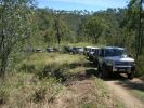
Start of easy hill climb172 viewsTR mode Rock Crawl - although I did turn off Hill Descent as the other side was not too steep and she wanted to keep slowing dramatically which I didn't appreciate in convoy. (Where is my old Pajero that had the inclinometer?)
|
|
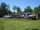
Rest stop after our first hill descent - line of cars stretched way back up the hill that disappears up to right of photo.201 views
|
|
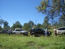
Rest stop after our first hill descent.191 viewsMode: TR Rock Crawl with HDC turned off as I found that the ABS kicked in too much. As we were in convoy I maintained a safe distance from car in front and just "feathered the brakes" as suggested by an instructor.
|
|
Chief instructor (left) and another instructor explaining water crossings204 viewsWhilst no one tested the waters this time (they did last week with another group) you can just see the stick floating in the water (near second instructor's right elbow). Satisfied that the rains hadn't changed the depth dramatically, they let us through - those that elected to take the water crossing of course.
|
|
Buckingham Blue goes through262 viewsRutted track to left of shot is where my car went rather than through the water. Mine still is only a few months old - maybe in 6 months or so I will try but at least I know that because other D3s did it on the day, I can when I am game enough!!
|
|
Last D3 through the deep crossing229 viewsThe water was stirred up by this time (didn't start off too clean due to heavy rains in the previous week) water was between 500 and 600mm deep depending on where the driver crossed. Away from the tree was slightly deeper but most drivers chose that line to be well clear of the tree.
|
|
Pipe91 viewsPossible pipe that leaks oil.
|
|
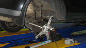
Bruce Davis Specialised Wheel Alignment Photo 280 viewsBruce claims that it is trial and error with standard wheel alignment equipment as you have to remove the wheel to make an adjustment and then recheck, a difficult task.
|
|
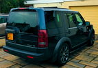
Almost there62 viewsA couple of other tweaks to add to the D Wagon and she will be as I want her. Still to match the side vent and Supercharger grill paint and considering a rear bumper valance and twin exhaust kit conversion. That should do the "Anti-Bling" nicely.
|
|
463 viewsFirst step in the journey, installed USB ports.
At the time I installed these, the goal was to use them in combination with the car-computer that resided in the back.
In the meanwhile, I dismantled the car-computer and nearly everything that was connected to it (touchscreen front, Wifi, DVB-T ...).
I kept the USB outlets in the front and turned them into charger for the appliances missus brings with her when we're on holiday. Mainly her iPod and smartphone ...
|
|

473 views@ home, we have 2 remote controlled garage doors. So I installed the remote controller in the car, added 2 buttons and off we go. Lucky me the controller worked at 12V anyway :D
I'll add a LED onto that one, so I'm sure it works when I press :)
|
|

533 viewsAdded an extra switch to the + leading to my PC and to the MP3 changer. As such I can cut off the power to both systems when needed. Learned that one after 2 days constantly working in the car, lighting the whole thing up during 2 days and noticed I couldn't start anymore :D. Saved by my wife's Freelander next to me :)
Also to be seen is the remote controller of the MP3-changer.
|
|
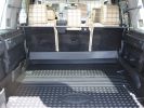
Paddock dog guard view from rear - with LR "high" mat fitted314 viewsYou can see that there was no cutting needed here - but the mat needs a good shove in!
|
|
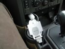
Set up in a cup holder...514 viewsRemember that my car is a LHD... There is a small suction cap to prevent the iPod from coming away to easily but it sildes "up" quite easily when you want to remove it... The Car charging adapter goes right behind in the provided outlet...
|
|
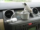
Full setup...563 viewsThis is a side view of that setup. As you can see, all the wiring can be hidden from view in the bottom of the car adapter (The part that goes into the cup holder...)
|
|
Close up...406 viewsSorry, this is blurry ! Oops...
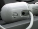
This is a close up of the adapter itself... There is a 3,5mm input for the connection to the iPod. There is also a volume button. I don\'t use this because of interference between my quite old iPod and that system. But it does charge the iPod through the dock adapter.
|
|
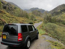
Glen Nevis253 viewsOn our tour of the Highlands and the Isle of Skye we ended up on a road that didn't seem to be on the map. It took us right up through Glen Nevis and then just carried on and on to the Falls of Steil (apologies if spelt incorrectly). The falls were amazing and were only about 1KM walk from where we ended up parking the Disco.
|
|

Ya don\'t wanna do that!410 views
|
|
The Thing !301 viewsGuess where it was build ? Let me just tell you that it does not rain so often then than here...
|
|

Wiring fault189 viewsThe wire and connector that corrodes causing a fault to the key fob locking
|
|

The clips (one completely broken, one partially, and one ok) that hold the plastic locking mechanism to the camera.31 views
|
|

Christmas Express50 viewsThat´s how christmas trees should be brought home!
|
|

Yes, thats right, it started first time!30 views
|
|
oooh thats tight127 views
|
|
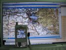
TTQV and PathAway on a Mac...384 viewsThat picture was taken as I was using TTQV from Touratech on a Mac running Windows XP SP2 under Parallels Software beta... The mobile is a Palm Treo 650 running PathAway...
|
|

153 viewsThat early morning Penshurst air!
|
|
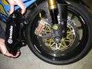
Smaller ones cost more118 viewsIt\'s hard to think that one of the small gold Brembos costs more than the complete set on my D3!!!
Stopping power of both is awesome!!
|
|
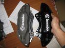
Brembos - FFRR vs RRS 01131 viewsHaving acquired the wrong calipers and discs initially, I purchased the correct RRS kit from TLO. Useful picture - the light grey calipers show that the FFRR has a smaller offset mounting point and smaller diameter threaded holes. The glossy calipers are for RRS and fit D3 perfectly with correct offset and M15 mounting holes.
|
|

Up that hill!76 views
|
|
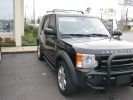
Front Passenger40 viewsI have a gaping hole where the winch that I don\'t have yet should be...
|
|

The Pulley that sheered off!!40 views
|
|

The Pulley that sheered off!!15 views
|
|

The Pulley that sheered off!!13 views
|
|
LRE Eastnor G4 D3581 viewsCALENDAR ENTRY
Photo taken during the LRW Show at Eastnor Castle, 6th June 2009.
The LR Experience G4 D3 was moving in to position to help out a stricken RR Sport that had gone off track and ended with its\' nose in the trees. A very impressive front (another LRE D3) and rear winching method to extract the RR Sport sideways followed.
|
|

52 viewsWho put that there.
|
|
32 viewsNew Christmas toy to try to learn the finer points of speed control over obstacles... Now I just need an LR3 body that will fit this monster...
|
|

DISCO 3 Porthallow Beach Cornwall 13 Aug 07 - CALENDAR 2008 ENTRY744 viewsCALENDAR 2008 ENTRY. Picture of my Disco 3 on the beach at Porthallow in Cornwall.
Picture taken in the height of the british summer on the 13th August 07 at approx 2:30 in the afternoon! (notice the hint of sarcasm there as even at that time of the day I had my lights on!).
Getting the car from where we were staying on to that beach was quite an entertaining drive, with the roads (more like lanes) only being just wide enough to fit the car through.
Hope you like it!
|
|
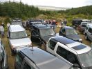
May 2nd80 viewsWho put that Suzuki there?
|
|
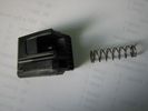
The bit that goes boing30 viewsParcel shelf
|
|
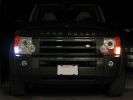
Comparison of the new white LED bulb and the existing incadescent bulb that I replaced.374 views
|
|

Close up of the 6-LED bulb that I used to replace the standard bulb.372 views
|
|
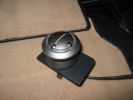
This is the controller unit that I attached to the emergency brake pop-out plate.386 views
|
|
This is the hole that I drilled to get the iPod cable into the center storage area.467 viewsThe hole needed to be this large as both ends of the cable are large.
|
|

UHF Antenna Mount384 viewsView from underside of bonnet. The lower half of the mount is folded from stainless steel and bolted through an exisitng oval shaped hole in the bonnet. This hole is throught the heavy steel plate that the bonnet hinges bolt to - not just the aluminium panel. A specially machined rectangular nut was made to pass through the oval hole, rotate 90 degrees and then stopped from turning by a slight shoulder on the nut.
|
|
the set up, camping : Caranex tent is really wet, thus that loosy style. otherwise it is GREAT651 views
|
|
EGR replacement29 viewsUndoing the right hand valve is much easier that the left one.....
|
|
EGR replacement19 viewsOpening up the actuator reveals that all was OK. Even the ball races are OK
|
|

100nM is not that tight.....11 views
|
|

Salisbury Plain. Nov 2012248 viewsApologies for the quality, some digital cameras are better than others. The plain is very wet currently, all due to that wonderful summer we had.
|
|
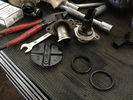
what you should be left with after the blanking procedure8 viewsApart from this, you'll also have to remove the pipes that connect the valves to the airbox. Not mandatory, but a proper job well done
|
|

DISCO3.CO.UK GET COMMISSION IF YOU ORDER FROM HERE http://www.craigsplates.co.uk25 viewsI AM GOING TO ORDER THESE FROM http://www.craigsplates.co.uk if that is ok. i see on the forum disco3.co.uk get a commission. Any issues with this?
|
|
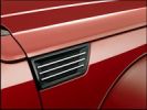
2007 Dodge Nitro - where did they get that design cue from?256 views
|
|

Interstate Battery Dimension sheet641 viewsThis sheet is hard to find - the sheet is not on the Interstate corporate web site but some dealer web sites display it. The pdf shows most of their available batteries including the H7 and H8 sizes that are the LR North America replacement batteries for the main starting battery. These batteries are of the Land Rover desired "shallow" cycle high discharge current Maintenance Free, (Ca Ca), internal construction, (not AGM, but instead, Wet Flooded Lead Acid with battery "caps" and Ca grid separators).
For the AUX battery , the H6, (BCI Group 48), is probably similar in dimensions to the Varta E12V75N that is popular in Australia. For that battery to fit in the second battery compartment, you must grind out the angled nibs on the inside front bottom of the LR black plastic surround, something I did wish to do and hence installed a Group 40R on a spacer. Alternately, one can choose an Interstate BCI Group 47 which is similar to a DIN H5 for the AUX location. I did this when I had to replace my 40R. No vertical spacer is required and the stock battery tie down bolts and clamp work well.
|
|

Part numbers for JAE connectors for the upper hatch switch. 382 viewsThis lists the JAE and Digi-Key part numbers for the electrical connectors for the hatch switch.
I contacted Japan Aviation Electronics and they directed me to Digi-Key in the USA who sell odd lots of the JAE product, odd lots meaning two pins and one connector if that is all you wish.
|
|

JAE connectors for the upper hatch switch and FAKRA connectors for the Sat NAV.539 viewsThis jpg shows some catalog pages listing the MX19 connectors used on the upper hatch switch.
Also shown are the FAKRA connectors that are used on the rear of the Sat NAV.
|
|

Replacement switch from RRS installed on LR3864 viewsThe switch shown is LR part number YUZ500020, the upper rear hatch release switch that is found on the Range Rover Sport.
The switch body is the same switch as on the LR3 except that there is no wiring disconnect on the LR3. Hence when the switch corrodes and requires replacement, the LR solution is to purchase a new handle and license plate light assembly. I instead cut off the old switch and installed a JAE mating connector to the existing wiring and hence just plugged the RRS switch in.
The replacement RRS switch snaps into the same rectangular space in the same manner as the removed LR3 switch, the difference is the JAE male wiring connector.
|
|
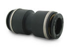
John Guest DOT all plastic fitting717 viewsThis is a picture of the John Guest DOT all plastic union. If you look closely, you can see the DOT imprinted in raised letters on the end of the fitting. This is of a 1/4" connector rather than the 6mm that the 3 requires.
The picture is similar to the air suspension pneumatic fitting union that Land Rover sells as replacement part # STC8580. This is for 6mm OD tubing size. The STC8580 comes with what are called "Collets" at each end that cover up the press to release feature underneath. See the John Guest web site www.johnguest.com under the Pneumatics section and also in Downloads for their catalog for install and remove instructions.
The actual "air brake spec" fitting that Land Rover provides has an interior 4mm OD ferrule that slips inside the 4mm ID of the nominal 6mm tubing. I have not yet been able to obtain the John Guest part number for the LR fitting, only the LR part number. This part number was generated for the RR Classic air systems.
|
|

John Guest (LR part # STC8580) push in straight 6mm tubing to tubing connector730 viewsThis picture is similar to the air suspension pneumatic fitting union that Land Rover sells as replacement part # STC8580. This is a 6mm OD tubing size push in to install straight tubing to tubing fitting. The STC8580 comes with what are called "Collets" at each end that cover up the press to release feature underneath. See the John Guest web site www.johnguest.com under the Pneumatics section and also in Downloads for their catalog for install and remove instructions.
The actual fitting that Land Rover provides has an interior 4mm OD ferrule that slips inside the 4mm ID of the nominal 6mm tubing. Hence the fitting depicted and part number are not actually correct. I have not yet been able to obtain the John Guest part number for the LR fitting.
The fittings that show in this doc are what I call food service fittings rather than transportation or Air Brake fittings. The part LR sells, (STC8580), is the Air Brake type for transportation.
|
|
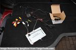
Everything thats included77 viewsCamera & GVIF and all cables after removal
|
|

Thread upload9 viewsImage uploaded in new thread
|
|

Just like that47 views
|
|

What\'s that coming over the Hill?82 views
|
|

Key in Ignition Electrical Wiring Diagram1051 viewsThis shows the key in ignition wiring, (LGW, 1.5D), running from the key lock cylinder to the Central Junction Box, (CJB), thru 5 amp fuse F40P, located in the fuse box behind the lower glove box door.
You can remove the 5 amp fuse and the good news is that the ignition chime will not sound any longer; the bad news is that a bunch of other circuits that rely on knowing if the key is in or out no longer work.
Also note the Transponder Coil D219 reference.
|
|

Modification so that the headrest is adjustable840 views
|
|

Modification so that the headrest is adjustable1022 views
|
|

Modification so that the headrest is adjustable821 views
|
|

Modification so that the headrest is adjustable1089 viewsmax. height
|
|

Modification so that the headrest is adjustable786 views
|
|
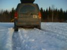
Snow is malting510 views Anything odd in the picture - except that snow is unfortunately melting away too early ?
|
|

GC is small409 views The new Jeep Grand Cherokee is not actually that Grand at all, it is quite small car.
|
|

thats a landcruiser under there!!!278 views
|
|

Thermostat Housing LR005631538 viewsWhen the time comes to install a new thermostat, consider installing the whole housing instead.
Advantages are the thermostat is correctly installed, (not as simple as it should be); you get all new plastic and that is important, plus a new coolant temperature sensor and also a new heater coolant bypass valve, the secret part no one realizes is also within.
The cost of the whole assembly is not much more than the cost of a factory thermostat and the effort to replace all is not as difficult as it might seem.
|
|
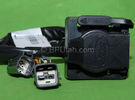
Harness section that runs behind the rear bumper.410 viewsThis is the harness section that clips up inside the rear bumper and includes the circular 7 pin, (6 flat +1 round), NAS socket, and also the 4 pin NAS flat connector.
The two small plug ends connect under the rear left tail light to the harness section that exits from the interior.
The Land Rover part number for the NAS trailer tow kit, (both cables), is YWJ500220.
|
|

Harness that connects inside left rear compartment.445 viewsThis is the harness section that connects behind the left rear interior access panel and exits thru the large grommeted hole to below/behind the left rear tail light.
Note the two rubber grommets on the harness as there is both an interior metal skin and an exterior metal skin behind the left tail light assembly.
The two light grey connectors plug into two existing connectors near the top of the rear left interior access panel. The two darker connectors plug into the second piece of harness.
There is no little separate fuse box either with the NAS spec harness. The fuse box is included with the UK 13 pin dual plug units. If there was a fuse box, it would be on this portion of the harness.
|
|

Littelfuse Add-A-Circuit MINI and ATO style data sheet150 viewsPDF from Littelfuse showing both the MINI and ATO style of fuse holders. The 3 uses the MINI size of fuse. The MINI Add-A-Circuit can be inserted in place of one of the existing fuse panel MINI fuses. The removed fuse is then inserted into the lower slot of the Add-A-Circuit and a second fuse in the second slot to protect the device that you are adding. The Add-A-Circuit is designed for a max of 10 amps on the second load, and I guess maybe the original circuit as well.
|
|
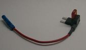
Littelfuse Mini Add-A-Circuit FMH200BP and OFH0200ZP1622 viewsFound this jpg somewhere on the forum - others are using them as it is a good way to tap the fuse box to add a fused circuit, or in this case, to modify a circuit to add a switch such that the fused circuit is switched. In my SmoothTalker gallery, there is a PDF from Littelfuse specifically related to this Add-A-Circuit device.
Before you install the Add A Circuit for any application, take an ohm meter and trace out the circuit path of the two pair of slots that fuses could insert into. The path is more complicated than one might first think. As such, the orientation of the fuse holder in the socket may matter depending upon the application. If the application is a circuit diverter, (as the F35 mode is), as opposed to a mere accessory adder, orientation matters.
|
|

LLumar "windscreen" clear Infra Red reduction side window film930 viewsThis is a data sheet on the LLumar brand of what they call Windscreen Film; It is almost clear, (has a bit of a blue tint), and reduces both the Ultra Violet fading and sun burn rays which most all films do as that is easy, plus more significantly, the Infra Red heat rays. That is rare as it is not so easy or cheap to do.
AIR80BLSRHPR (blue) is what the IR rejection film is listed as in the brochure that I used. http://www.llumar.com/en/AutoWindscreen.aspx
I had it applied to the front side windows as well as the front sun roof. One can feel the difference when the sun is low and streaming thru the side glass or high and coming thru the sun roof. Rolling a side window down is the simplest test of effectiveness re the rejection of the heat energy.
|
|

LR Electric Trailer Brake C2590 Female Connector606 viewsThis female connector, C2590, located up above and near the brake pedal is for the Trailer Electric Brake Controller hookup.
The Black wire in the bottom right is pin #3, the ground. The Blue wire to the left is pin #6, the Trailer Brake Controller output going to the rear trailer socket.
The White #4 wire is the 30 amp fusible link, (Link 6E in the engine compartment junction box), for the Brake Controller 12VDC power feed from the battery. Note that this would make a pretty good power source for CB radios and the like if no electric trailer brakes were required.
Pin #5 is a Green wire from the stop lamp switch, (the control input for the Brake Controller).
This plug is standard on all NAS (LR3) vehicles, but unlikely to be found on the D3 spec units.
|
|
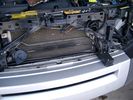
19mm wiring loom in trough behind bumper and in front of rad792 viewsThe 19mm wiring loom is large enough that a maximum of six 6mm air lines can be fished thru as required. The loom runs from the FASKIT panel located in the engine compartment behind the left front headlight, down and across in front of the rad and then down to the front axle valve block located behind and below the right fog light.
|
|

LR3 Air Conditioner Drain Tubes behind centre console2132 viewsThis shows the two air conditioner drain tubes located left and right under the radio stack.
The tube on the left side, (steering wheel side, LHD), disattached itself and the carpet on the floor under the gas pedal etc became soaked. I think rain water from outside that comes in the outside cowl vents also exits via the tubes as I first noticed the carpet was wet after parking outside during a big rain storm.
It was relatively easy to slide up and reattach the rubber hose that runs from the rectangular shaped plastic discharge hole(s) of the heater "pan" down along the transmission hump area and thru the floor pan. There is a hose on each side of the transmission hump, but only one hose had let go on my 3. The rubber hoses just slide over the rectangular plastic openings of the two heater housing drain outlets.
To get at each drain hose, remove the vertical sort of triangle carpeted piece below each side of the radio stack. The triangles of carpet will just pull away as each is held on with those metal U clips Land Rover so likes. Dislodge each triangle at least sufficiently to get ones hand in to slide the rubber hose back on.
You will rarely see AC water on the ground as the front drains pour onto a metal underside protection skid plate and the rear drain onto the top of the left rear muffler.
|
|
Air Suspension ECU Fuse 35P cut off switch.3821 viewsThis shows the SPST rocker switch mounted in the blank plate installed in lieu of a manual passenger side air bag shut down switch - now automatic via passenger seat pressure switch. Fuse 35P (5 amps) is located in the interior fuse box behind the lower glove box and protects the ignition power supply to the Air Suspension ECU. When the SPST switch is moved to the OFF position, the RAISE /LOWER switch on the centre console is not powered, and hence does not function. As such, some signals from the wheel height sensors and CPU are ignored. By itself however, removing F35P will probably not stop the 3 from self dropping, particularly after the engine is turned off.
Fuse F3E, (5 amps), located in the engine bay fuse box by the starting battery protects the circuit that provides feedback to the Air System ECU indicating that the Compressor Relay has successfully operated and that the Air Compressor is or should be operational, can also be removed, (but is probably not totally necessary), as it gets its power thru F26E. Hence Fuse F26E, (20 amp), also located in the engine compartment fuse box is the fuse that must be removed. This fuse protects the circuit that provides full time battery power to the Air System ECU. When in place, current thru the fuse powers the periodic re-levelling action, (usually lowering a bit with that brief air release noise), that often occurs when the vehicle is parked and the engine is off.
Removing F26E fuse will stop the auto levelling action and also inhibit any other down to the stops signals, (engine running or not). When F26E is removed, no power can flow thru to F3E, hence removing F3E is more for insurance than an absolute requirement. The same with F35P, removing F26E removes primary full time power from the Air Suspension ECU, and hence removing the F35P fuse should not really be required either as long as F26E has been removed.
|
|
Air Suspension ECU Fuse 35P Shut Off Switch2635 viewsA more distant view of the shut off rocker switch in the ON position which is the normal position for when all is working as Land Rover intended.
Ideally, (but not totally necessary), the F35P circuit should be powered or de-energized after the various computers have gone to "sleep".
Similarly, removal of the F26E or F3E fuses is preferable after the computers have all gone to sleep but it appears that no real damage will be done if the fuses are removed while the system is energized. Pulling F26E is the main full time fuse that powers the air suspension computer. As such, once F26E is removed, pulling F3E is not really required.
Power for the compressor goes thru the 60 amp fusible link and relay, however control of the relay is via the air suspension computer so depowering the air suspension computer effectively depowers the air compressor and the internal exhaust valve relay/port.
|
|

Battery Maintainer pigtail sticking out of Grill728 viewsThis is all you see when everything is put back together - just the pigtail and Weather Pack blanking plug. Most often, I have it all tucked back behind the grill.
In winter, there may be a second cord hanging out as well - the 120 VAC power cord for the engine block heater, a tea kettle like element inserted in the engine block. NAS petrol V8's do not have the Fuel Burning Heater, (FBH), installed, but instead in cold area markets have the block heater element assembly available as a dealer installed option. There is an argument to say that the heating element is factory installed in all cold climate V8 gasoline engines, however the appropriate power cord is not. If true, this means that all one needs to purchase is the area specific power cord and plugging in / attachment to the engine block located block heater.
As such, you will often see a conventional 120VAC three prong power plug hanging loose out of the grill of most vehicles here in the wintertime. In summer, most drivers tuck the plug back behind the grill as it is no beauty mark.
|
|
Battery Maintainer switch box and connector 723 viewsThe Hammond box contains a DPDT toggle switch with centre off. The Positive and Negative from each battery feeds to the switch. Depending on the setting of the toggle, (full left, full right,or centre off),the respective batteries connect into the pigtail that can stick out thru the grill when one wishes to connect the charger.
This allows one to charge each battery independently via a suitable battery maintainer. I use a CTEK unit that feeds a maximum of 3.3 amps at 14.4 or 14.7 VDC, depending upon setting. The wiring therefore allows for a slow recharge of either of the batteries separately if either one requires such.
|
|
Battery Maintainer switching box plug and CTEK Multi US 3300 charger. 706 viewsThe CTEK Multi US 3300 maintainer is just sitting there for the picture. In addition to topping up both batteries, the CTEK can provide power such that if the batteries were completely dead, there would be power to the door locks and hence, one could most likely still gain access via the remote once the starting battery charged up a bit.
The Land Rover recommended method is via the hidden key hole which is mechanical, however that presumes the mechanism is not frozen from lack of use. As such, the manual lock should be exercised at least once a year to ensure that it still functions.
The blanking plug sitting on top of the plastic box is of the GM Weather Pack series. That is what I like to use for vehicle wiring that is subject to moisture, (or not).
|
|
Boot lighting, looking to rear - hatch closed 543 viewsView shows the lights mounted in the rear on an early spring day.
In operation, the lights are tilted so that they shine downwards. The lights are mounted high enough up that one cannot see the LEDs from the front thru the rear view mirror; also the LEDs are so directional, that no light is thrown on the side glass.
Each assembly contains 15 LEDs, however the reflector is such that the LEDs appear to double.
|
|
Boot lighting panel, finish side up 310 viewsThe above jpg shows the two 15 LED light assemblies as well as the SPST rocker switch mounted beside the W5W Land Rover supplied light.
The reality is that with the recent development of LED lighting that can replace a W5W T10 bulb, one can almost achieve the same results just by installing a LED bulb within the factory light.
|
|
Compressor Air Drier 2044 viewsA view of the air drier - the black round thing to the right of the actual compressor cylinder head.
The general feeling is that the air dryer is responsible for most of the compressor problems now and that replacement of either the assembly or just the beads inside will probably revive one's compressor. In reality, the beads may have for the most part broken down and turned to dust plugging the internal filters. Hence replacement of the complete dryer unit has some merit.
The part number for the dryer assemble complete with the desiccant is VUB504700.
|
|
Compressor Con Rod Broken 1753 viewsThe model number of this compressor is RQG500060; the model number of my replacement compressor was LR015303, the unit that was apparently being installed on the D4 vehicles as of Spring 2010. As of Fall 2011, the new replacement part number is LR023964, the same as in the 4's.
Note the number hand written on the black plate. All the compressors seem to have some number hand written on them - hand built I presume, and every unit perhaps evolving a bit differently as LR struggles to build a compressor that will last. I guess Hitachi, (the manufacturer), should be given credit for that.
|
|
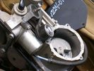
Compressor Con Rod Stud 1342 viewsVisible in the expanded view of this picture is the worn rounded threaded screw that tied the con rod bearing to the electric motor eccentric. I think the stud unscrewed itself and pulled out; then the piston jammed and the con rod broke.
|
|
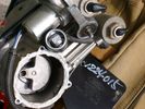
Compressor Exhaust and Inlet 1534 viewsThe two temporary black plugs cover off the 8mm and 10mm push fit lines to the air inlet and exhaust lines. Also visible is the worn threaded stud that I think was the initial failure mode.
|
|
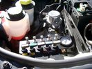
View of mounted panel from front left side878 viewsNote that all valve handles are shown in the OFF position, (the trouble position). In this case, the air that is in the air springs, (if any), is trapped in there - that is the valve blocks cannot vent whatever air is already in the air springs as the air lines between the springs and respective valve blocks are closed off by the FASKIT valves. In operation, there may be only trouble with one air spring, (perhaps a wheel height sensor), and as such, only one valve would need to be closed. If there was complete air compressor failure, then all valves would be closed and then as required, each spring could be manually filled from an outside clean dry oil free air source.
|
|
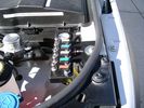
View from front left side looking towards rear aux battery compartment under cover 647 viewsAs there is no Fuel Burning Heater in the NAS V8 petrol vehicles, there is space available to install the FASKIT panel here. The piping is such that each air spring can be isolated from the air system and then filled one at a time manually via the Schrader valve. There are five Schrader valves and five shutoff valves. The fifth valve nearest the gauge controls air from the compressor, and can provide fill up air via a jumper fill line assuming the compressor is still operational.
|
|
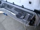
Dust Seal duct taped back together 2281 viewsThis shows the dust seal duct taped back together; also the surplus wire rope exiting from the actuator area prior to being cut to length.
I do not think the sticky plastic membrane is a dust seal, but more of a cable protector to cover up the wiring bundle that is effectively sticking to the underside of the flexible membrane.
|
|
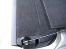
Flexible wire rope fishing leader 0.032" diameter exiting carpet 1948 viewsThis is all you see of the completed mod.
The short little angled "line" about an inch long that looks like a piece of debris and is located a few inches "above" the support cable is actually the wire rope release cable exiting from under the carpeted lift gate cover.
I drilled a very small hole in the carpet and pushed the 0.032" diameter release wire thru and then slipped the loose end under the black plastic.
To release with the lift gate etc closed, from the inside, just pull the loose end free from under the black plastic and gently pull wire about 5mm, (1/4"), and the upper door catch should release. You will have to manually push the upper door out wards to actually effect opening, but you will already be inside the rear cargo area so that part is easy to do.
The assumption is that the lower door latch still works electrically and hence, the lower lift gate half will open as normal by pressing the usual button on the top left of the lower door half.
|
|
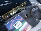
0.032" OD metal fishing leader and lead fishing weight clamped to existing wire rope 2121 viewsI used a size #0 lead fishing weight as a clamp to attach the 0.032" diameter flexible wire rope fishing leader to the release cable.
The pictured weight is the smaller #00 weight, however it did not work very well so reinstalled with the larger #0 size. I clamped to the cable as what breaks is the L retainer that is hidden in the actuator and holds the cable. When the L breaks, it lets go of the cable so you hear the clicking but there is no opening action.
Clamping on to the cable is an attempt to resolve that reality; also if the actuator electrically fails, the release mod should still do the task. Note in the picture the two Torx T15 screws that hold the gold plate to the plastic case and also the two 8mm cap screws that have to be loosened to remove the actuator from inside the door.
|
|
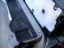
Carpeted cover removed showing uncut dust seal and underside of carpeted cover. 1628 viewsNote that there are all sorts of electrical wires sticking to the underside of the dust shield - so be very careful when you cut thru the shield.
I used a box knife very slowly and was surprised at how many conductors there were running just under the shield membrane.
|
|
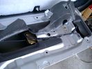
Dust seal cut; note electrical conductors right under dust seal 1627 viewsShows what is underneath when the dust seal is cut. Note the electrical conductors.
I used a box knife to cut the plastic and it was at first easy; then I seemed to hit something and fortunately I stopped - it was the wires - lots of them stuck right to underside of the sticky seal material.
Also shown are the two 8mm nuts in slots that you only have to loosen to release the gold actuator assembly.
|
|
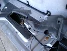
Dust seal rolled back showing electrical conductors 1658 viewsNote power conductors just under the dust seal which makes cutting the seal more interesting.
Also shown are the two 8mm nuts located in slots. One must loosen each nut to effect removal of the actuator. This will then reveal two T15 Torx screws that one must completely un-thread to remove the top gold plate from the actuator assembly.
|
|

LR3 Electrochromatic Interior Rear View Mirror wiring diagram.853 viewsIt seems that there are two fuses, F69P and F5P that provide power for the interior rear view mirror. Ten amp F5P is a feed off the reverse gear relay and inhibits auto dimming when reverse is selected. Five amp F69P provides power to the auto dimming circuits and the garage door opener function if optioned.
The pdf can be downloaded and printed out. For on screen viewing, right click on the pdf and select the Rotate Clockwise button.
|
|
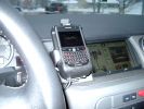
Blackberry Tour mounted on air vent showing default analogue clock 213 viewsA characteristic of the Blackberry is that when charging, the display can default to an analogue clock. Hence when the unit sits in the holder, the phone is being charged and the analogue clock displays. When the phone rings, the clock disappears and the call id displays.
|
|

LR3 Sparkle Silver 6 spoke Wheel Cromodora of Italy 19 inch x 8 ALY72191U1108 viewsThese are the standard equipment 19" wheels on the 2005 LR3 HSE. The wheels are Made in Italy by the Cromodora company. Each are rated at 940 kg (2,072 pounds) and have an offset of 53 mm positive, (53P or +53).
I mention the 940 kg load rating as that is about the heaviest rating of any Land Rover product. The RRS and RRHSE both have lower ratings. What this means is that while a wheel from a Range Rover may physically fit, it probably does not have the brute strength of the factory spec Land Rover 3 wheel. There is no Land Rover product heavier than the 3, hence the 3 wheel design spec is the heaviest of the bunch.
|
|
LR3 Sparkle Silver 10 spoke Wheel Cromodora of Italy 18 inch x 8 ALY72190U727 viewsThese wheels are factory standard on the 2005 LR3 SE and Made in Italy by the Cromodora company. Each wheel is rated at 940 kg (2,072 pounds) and has an offset of 53 mm positive, (53P or +53).
I mention the 940 kg load rating as that is about the heaviest rating of any Land Rover product. The RRS and RRHSE both have lower ratings. What this means is that while a wheel from a Range Rover may physically fit, it probably does not have the brute strength of the factory spec Land Rover 3 wheel. There is no Land Rover product heavier than the 3, hence the 3 wheel design spec is the heaviest of the bunch.
|
|

Wheel cut thru definitions and specs898 viewsNote the location of REAR SPACING and also OFFSET; probably two of the most important dimensions and not always understood as related to wheel size and relationship to the brake components.
For the 3, Rear Spacing is approximately 6.5 inches or 165 mm for a nominal 8" rim. Offset is 53P or 53mm Positive, which means the distance from the machined hub flat mounting surface to the rim's true centreline is 53 mm in the outboard direction. (The rim illustrated has a negative offset.)
As Positive offset increases, this means the wheel wraps around the disc brake mechanism more deeply, and hence the more the wheel would cover the brake parts. This is why most 18" wheels will not fit with the larger Brembo "supercharged engine" brake calipers.
Pitch circle diameter is 120mm; Pattern is 5 lug, and the tyre load rating is 112 with a recommended tyre speed rating of H or higher along with the XL load rating. For the 3, the stock tyre diameter is about 30 inches. The 255/60/18 or 255/55/19 OEM tyre outside diameter is 30.04 inches; Wheel lug torque is from 130 to 150 Nm or 96 to 110 lbf-ft and the lug nut hex socket size is 22mm.
Max Load High Speed Driving Tyre pressures are Front, 33 psig, (230 Kpa) and Rear, 42 psig, (290 Kpa).
The OEM rims are rated at 940 kgs, the highest that LR makes, hence while rims from other Land Rover products may physically fit, the odds are they are under rated in a weight sense.
|
|

Underhood Fuse and Relay Box drawing 3055 viewsShows the various fuse and relay locations. Fuse 3E, (5 amp), and Fuse 26E, (20 amp), as well as upgraded 70 amp Relay 7, part number YWB500220, locations are displayed. Relay 7 sends battery power to the compressor from the 60 amp fusible link called up as 10E. Fuse 26E is what provides full time always on battery power to the air suspension ECU and hence powers the auto level wakeup when the vehicle is shut down and say parked for the night. Removing F26E is the primary method to disable the air suspension system; Removing F35P is more if you want to experiment with it from inside.
I found it useful when I had a suspension problem, (actually a wheel alignment problem picked up by the steering wheel angle sensor), that only showed itself on the highway but allowed for no trouble light driving in the city. This was because in the city, the steering wheel was always in motion and rarely was the vehicle driven in a near straight line for very much distance.
|
|

lr3-kaymar-closed with 20"405 viewsthe kaymar carrier, designed to allow two tires, sets them both a bit outboard, thus blocking the lamp. that\'s when I realized why they put the fully functional lamps in the bumper (functions: running, brakes, signals, hazard)
I plan to re-weld the locating section more towards the middle of the rear similar to Disco II orrientation.
|
|
wiring progress424 viewslots torn out that somehow goes back together
|
|

Ashtray Slide6 viewsThis is a quick drawing describing how the ashtray stays in. There's a pin that rides through this channel, gets caught to stay closed, and pushing t in releases the catch.
|
|

LR3 Denso Alternator YLE500390 pulley view819 viewsNote the DENSO sticker on the side. Denso calls their nominal 150 amp 12 Volt alternator an SC2 design. SC means Segment Conductor which apparently increase the winding density of the stator coil, hence yielding a physically smaller lighter alternator for a given output. I presume the 2 means the second try at getting it right. A Denso part number is 4280003690 for the alternator, (there are others, as below).
Rotation is clockwise and the 54mm diameter pulley has 6 grooves (PV6x54). Count the pulley grooves on both the one you remove and your new one - some replacement alternators seem to ship with 5 or 7 grooves so you might be swapping pulleys.
A previous LR part number was YLE500190 for the older variation of the newer YLE500390 unit.
An additional part number for a factory rebuilt is Nippon Denso 210-0569 for the petrol V8 alternator. Other Nippon Denso numbers include 104210-3690 and 104210-3691. The Lester number is 11206 which relates to another Denso number of 290-5287. WAI uses 11206N.
From 2006 to 2009, the internal regulator is a Transpo IN6349 and of the B circuit type if it can be said that applies to PWM, (Pulse Width Modulated), regulators.
The "regulator" inside the alternator is therefore really not a regulator in the old sense of the term but instead an instruction receiver from the ECM that translates Pulse Width Modulated (PWM) signals into a form that the alternator understands – digital like signals from the Engine Control Module(ECM) into analogue like signals that the windings understand.
|
|

LR3 Denso Alternator YLE500390 rear view709 viewsThis picture shows the rear of the YLE500390, the Land Rover part number for a newer design alternator utilizing the Transpo IN6349 regulator with the "hidden" cooling fins. Note the visual difference in the rear view of the next file jpg.
If the alternator is a rebuilt, (service exchange unit), but Land Rover supplied, then the part number is LR008860 or similar. (Note that 0 in LR0 is zero.)
Two Denso part numbers exist for the alternator as well, 4280003690 and 4280003691. The rating of the petrol V8 alternator is nominal 12 VDC and 150 amps. In normal day to day operation, they seem to run about 14VDC - usually between 13.9 and 14.1 volts at the OBD port.
For the petrol V6, the LR service exchange number is LR008862, and the 2.7TDV6 is LR008861.
The bridge rectifier within the alternator is a 12 diode avalanche type, 117mm diameter, as used in Nippondenso 120 to 160 amp alternators with the Hair Pin stator. It is similar to a Transpo INR421 which is rated for 120 to 150 amp alternators. That is probably our primary problem - the rectifier is just too light. Alternate part numbers for the bridge rectifier are Cargo 237607, Mobiltron RM-29 and AS ARC6021.
Re the B+ stud, the INR421 calls it up as an M8 x 1.25 x 30 mm long course threaded stud; some say 34 mm but that may be longer than desirable.
|
|
![Filename=LR3_BMW_Ford_ZF_6HP26X-28X_Catalog_with_metal_pans_[1].pdf
Filesize=1194KB
Dimensions=320x240
Date added=26.May 2011 LR3_BMW_Ford_ZF_6HP26X-28X_Catalog_with_metal_pans_[1].pdf](images/thumb_pdf.jpg)
ZF 6HP26X and 6HP28X transmission parts showing various pans2814 viewsThis 42 page pdf is probably the most informative of all the material in this album. It is called a spare parts catalog but is much more than that. The material is specifically for the X variety of ZF six speed transmissions that are in the Land Rover 4WD / AWD models as well as BMW and Ford AWD vehicles.
|
|

Land Rover Brake Light switch XKB5001102700 viewsThis is what the switch looks like when removed from the parts box. Note that the plunger is recessed back into the body and when installing, the process of rotating the switch body 1/4 turn anticlockwise releases the plunger so it pops longer and engages the brake pedal. If you look down on the plunger you can see curved slots where the rotation takes place.
Do not try to rotate the new one - play with the one you remove. Also do not press on the brake pedal when removing or installing as you will damage the plunger - this is one of the reasons the plunger is retracted into the body for installation. It is also for this reason that if you try to confirm the operation of the switch contacts with an ohm meter by pressing the plunger, the switch will appear not to function as one might anticipate. Have faith, the switch will however, once installed and the plunger is in full motion.
|
|

LR3 Brake Wear Sensor Wiring1517 viewsThis 1 page wiring diagram pdf shows that both the front and rear brake pad wear sensors are part of a closed series circuit to ground.
In operation, when all is good, the series circuit is grounded and the amber brake wear warning indicator on the instrument panel is not illuminated.
When the pads on one wheel, either the left front, or right rear, become too worn, the respective sensor is "cut" which results in an open circuit condition. This causes the dash brake wear indicator to illuminate.
The circuit is like the old style Christmas light strings where one burned out bulb caused the whole string to go out.
A quick field fix to get the dash light to extinguish in lieu of replacing the sensor and pads etc is to disconnect the brake pad wear sensor and short across the two open conductors of the vehicle side connector plug. This of course means you now have a normal vehicle, one of the thousands that do not feature brake pad wear information systems.
|
|

Power Door Lock wiring diagrams530 viewsI thought I would include this 5 page power door lock wiring diagram pdf here as well.
When the pdf loads, if the views are vertical, it may be that you can right click on your mouse and a box will come up that will allow you to rotate the views clockwise so that the sheets are horizontal. Alternatively you can download the file and print each sheet yourself.
|
|

Horn Wiring Circuit LR3578 viewsThe is the wiring diagram for the dual horn circuit.
The Horn Relay, (R133), is not a big black thing hidden somewhere but instead what is called a FET, (and it is hidden)!
This is a Field Effect Transistor that is built into the circuit board that is mounted to the back of the fuse box that is located behind the lower glove box door on the passenger side of the 3. The related 15 amp fuse, 12P, is mounted in this fuse box and is often called F12P, where F is for fuse, and P is for Passenger compartment.
This is to help differentiate from another fuse and relay box, (the usual kind), that is located beside the starting battery in the Engine compartment. FxxE is often used in the naming of those fuses.
|
|
![Filename=LR3_Radio_Removal[1].pdf
Filesize=190KB
Dimensions=320x240
Date added=04.Feb 2014 LR3_Radio_Removal[1].pdf](images/thumb_pdf.jpg)
Radio Removal from Radio Stack571 viewsThis shows how to remove the radio from the stack. Basically you remove the H surround first and then at least loosen all the Torx 20 screws left and right sides from the top down starting at the narrow unit that the four way flasher/locking buttons are mounted on.
The units kind of interlock, hence some movement of each is required to remove the radio by itself. I find it best to take out the four way flasher/locking buttons assembly first as that allows access to the fibre optic cable connector into the back of the radio head without too much tugging.
|
|

Stop Light Lamp Circuit pdf2491 viewsThis pdf shows the brake light circuit for the NAS LR3.
Note that power for the brake light bulbs can come either thru the brake light switch power feed /contacts plus also from the Hill Decent Control, (HDC), system relay located within the Central Junction Box, (CJB) - yes two separate sources of power for the brake light bulbs. This would tend to explain how a brake light circuit concern shows up as a hill decent fault message; also why lesser vehicles without hill decent braking mechanisms, (HDC), never display this sort problem when a brake light bulb or switch acts up. You never have a problem related to a system that does not exist.
Additional evidence of the relationship of the HDC and the tail light circuit is demonstrated by when the HDC actually acts to slow the 3 down, the brake lights automatically illuminate even if the slowing action was merely retarding the engine speed or shifting to a lower gear, (in other words, no foot on the brake pedal).
There is also a tie in to the Cruise Control and hence a failing brake light switch can affect cruise operation or just create false Cruise Control messages. To further complicate the issue, while there are no messages generated, operation of the radiator electro viscous fan can also be negatively affected by the fouled set of secondary contacts within the brake light switch. This is all because the NC contacts within the brake switch send misleading messages to the ECU.
While the ground wire design is similar to other vehicles, note the grounds for the brake light filament and the reverse light filament are common on each side. That means that if one has a non functioning brake light on one side, the reverse light may not also work or that some problem with the reverse lights could back feed into the brake lights. This situation while unusual, can result when grounds are corroded probably due to swimming in rivers and creeks or just routine driving in a marine environment.
|
|

ZF 6HP26 transmission fluid drain and refill procedure4040 viewsThis is the Land Rover instruction pdf and I note they have it right - that is remove the filler plug first, then the drain plug. Also before you attempt that, not only do you need oil, but also new fill and drain plugs as the sealing washers are deemed single use only.
|
|

ZF 6HP26 Land Rover Transmission specs1677 viewsThis is just two sheets of paper with various numbers related to the 6HP26 such as oil capacity, gear ratios, and torque wrench settings for the fill and drain plugs.
You may note that LR calls this ZF transmission the 6HP26 whereas ZF calls out the LR3 transmission as the 6HP26X. Just what the differences are, I am not certain however the X refers to 4WD or AWD use as opposed to solely 2WD.
Zahnradfabrik is what ZF is short for and translated from German, roughly means Gear Factory.
|
|
Pumped Up Freelander on Roych192 viewsJust to prove that Freelanders really can do Roych
|
|

Articulation at the top of Pindale265 viewsThe guy in the green was genuinely rocking me side to side - I reckon that rear wheel was a foot off the ground
|
|
Main starting battery showing 1/2" hole drilled for power cable egress910 viewsView of OEM battery in Left Hand Drive LR3. This is supposed to be a Battery Group BCI 49 or H8 sized battery but in reality is the slightly shorter BCI 94R or H7 battery that fits easier lengthwise, (12 3/8" vs 14").
Note the 10mm hole drilled in plastic of surround to allow for entry of main power cable that runs between batteries. The cable bolts to a spare 6mm threaded hole in the OEM battery cable end; the light gauge wire runs to the front of vehicle to a connector for the CTEK MULTI US 3300 charger. Coloured felts, (red and green), are a material treated to reduce battery post corrosion. The OEM battery ground cable is only about a foot long and runs to an 8mm stud located on the inner fender just to the rear of the fuse case.
|
|
Main Battery showing aux cable feed running off positive battery post.776 viewsThe black wiring loom around the battery cable to the aux battery was a part provided with the Traxide kit. My goal was to run the cable low enough such that the battery box cover would go back on as previous.
Note the hole drilled in the side of the battery box such that the new cable could thread thru to allow the battery box top to still fit the same as prior to the addition of the cable to the auxiliary battery.
|
|

66 viewsThe cover that you remove to access the cable, for manual release of the electronic parking brake.
|
|

Australia Compared188 viewsJust so that others get some idea of the magnitude of the Canning Stock Route (see RichardK's gallery). It is 2000 kilometres on unsealed roads. On top of that is the journey on the sealed roads from and to home. Japan is only a couple of thousand kilometres from top to bottom.
|
|

Thread upload12 viewsImage uploaded in thread 158956
|
|

Yes, that is Marilyn in better days.1594 viewsIf she had just been content to fool around with blokes who liked Land Rovers ...
|
|

PDF of Mini Fuse data re LR3 / Disco 3 fuses.1854 viewsThis is just a data sheet regarding the MINI fuses that are common in the 3.
|
|
thats more like it62 views
|
|
Really funny (if you can read chinese that is)56 views
|
|
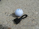
MOST fiber optic loop tool469 viewsThe looping tool in the jpg uses the Land Rover type plastic fiber optic cable with both ends feeding back into a female fiber optic connector that mates with the male fiber optic connectors on the Land Rover system.
The purpose of the loop is to allow one to disconnect MOST connected items such the BlueTooth module or the HK amplifier but allow the MOST system to still transmit signal from the head unit as the circuit would remain closed and hence complete. Of course with the Bluetooth module disconnected, there would be no Bluetooth available, however the radio and NAV would still function.
The looping tool allows one to troubleshoot the system by removing one component at at time from the MOST loop. In other words, what might appear to be a radio problem could be a Bluetooth problem - that sort of thing.
|
|
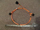
Fibre Optic MOST cable between components.560 viewsThis is a typical section of Plastic Optical Fiber (POF) optic cable with the orange coloured cladding covering the perimeter of the light transparent core. This is used as the MOST (Media Oriented Systems Transport) data transmission medium.
Note that each MOST 1355426 optical connector holds a pair of light conductor cables, one transmitting optical signal in, and the second, optical signal out. When connected to the other cables and devices, the cables form a continuous loop.
The light signal within the cable is red colour as one might expect. One break or disconnect anywhere along the loop shuts down signal transmission to all the connected components.
|
|
Wow, now thats a great view122 views
|
|

Mt Tamborine - panorama181 viewsPhotos taken on run into northern New South Wales - Hang gliders launch from here. Compiled from 5 images stitched with AutoStitch, a freeware application in development - superb application that requires little input other than reasonably good images.
|
|
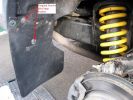
Fitting Land Rover Series 3 Rear Mud Flaps to a Disco 3/4 - A956 viewsUsed Original Screws plus two extras, Had to cut around exhaust. Once first done, laid them back to back and used first as a template to drill and cut second. Used a 5.5mm drill for the holes in the flap for the original screws and a 7mm drill to make the new holes in the plastic wheel-arch trim and lining to take the two-part trim clip (see my gallery for a picture of this style clip) - this photo of the new flap shows two screws but I modified that design to avoid using screws which corrode with time. Ignore the fact the pics are taken on a D3 Coiler, it makes no difference.
|
|
After replacement heavy duty coil springs fitted129 viewsReplacement King Spring coils fitted 22 February 2008. Oem shocks retained.
Wheel arch measurements (note that the old springs - weighing perhaps 30kg - were sitting in the boot when the "after" measurements were taken):-
FRONT
Before - 33" (84cm)
After - 35¼" (89.5cm)
REAR
Before - 33" (84cm)
After - 34¼" (86.7cm)
|
|
After replacement heavy duty coil springs fitted188 viewsReplacement King Spring coils fitted 22 February 2008. Oem shocks retained.
Wheel arch measurements (note that the old springs - weighing perhaps 30kg - were sitting in the boot when the "after" measurements were taken):-
FRONT
Before - 33" (84cm)
After - 35¼" (89.5cm)
REAR
Before - 33" (84cm)
After - 34¼" (86.7cm)
|
|

Rear wheel arch measurement after replacement heavy duty coil springs fitted146 viewsAfter replacement heavy duty King Spring coils fitted 22 February 2008. Oem shocks retained.
Wheel arch measurements (note that the old springs - weighing perhaps 30kg - were sitting in the boot when the "after" measurements were taken):-
REAR
Before - 33" (84cm)
After - 34¼" (86.7cm)
|
|
The Flatness of Delftland58 views
|
|
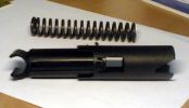
Mystery part that I found under drivers seat263 views
|
|

How to cable factory BT module (including MOST bus connector)85 viewsInstructions to install Factory BT module in a Disco 3 that has LR aftermarket or no BT module installed
|
|

First Discovery10 viewsA battered-to-death-by-farmers and then brought-back-from-the-dead 300TDi Disco. When first seen the driver's seat was a plastic crate. Resprayed in Eastnor Green with replacement front seats and steering column controls that had been chewed off by farmer's dog. In many respects my best Land Rover buy ever!
|
|
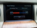
separate vol control for direction voice33 viewsthere are many voice options one of which is a chinese donald duck ..no really thats what its called
|
|
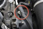
Tie-Wraps774 viewsWhen the EGR pipes are removed, you lose the brackets these cables are normally secured to because the brackets are part of the pipes. This is my solution to the problem - refit the bolts with an almost closed tie-wrap around them, then slip a new tie-wrap through the loop on that one and around the cable.
|
|
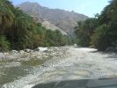
Not much water here!143 viewsThe last rains in this area were in June and photo taken in October. Water does run, but its very dangerous in the flash floods that follow rain in the mountains.
|
|
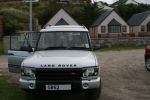
Picture of old bus just prior to trading it in .... Jan 03 S model 35000 ish on clock - Had the infamous problem with liquid ingress on injector loom but after that was great car128 views
|
|
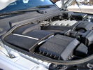
Overview of engine compartment from Main Battery side, (Passenger, LHD), looking across to Aux Battery753 viewsNote labels on main battery cover. The one you cannot read says that an auxiliary battery is installed on the other side. This is to warn service people should they wish to shut off all battery power.
The main starting battery is supposed to be of CaCa separator construction and DIN H8 or BCI Group 49 size. This means Calcium separators Wet Flooded Lead Acid, 13.9" long, 7.5" high and 6.9" wide.
On the Aux battery cover is a label saying to disconnect the blue Anderson single pole connector located under the cover by the brake reservoir. BCI Group 40R battery is small enough that the cover goes back on.
|
|

140 views
|
|
Secondhand Minilites?202 viewsI wish that these were available for the Discovery 3 in 8x17 or 18" sizes.
Lots of secondhand tyres and rims stacked around tyre and motor car dealers yards everywhere we went in Japan from Hokkaido right down to Kyushu.
|
|
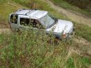
Andy stuck147 viewsPicture is a bit deceptive here - the ruts are so deep that the D3 is bottoming out.
|
|

Toyota IST - almost a Love Child of MB Parents175 viewsDiscovered that this is a Toyota Ist; it comes with a 1.3 or 1.5 litre engine with the 1.5 also available in 4WD. It seems to be a popular car for customising in Japan as there are a number of sites devoted to that.
|
|
Closeup View - Honda CBR193 viewsShowing feathered edge on a bike that is obviously ridden like the rider stole it!
|
|
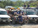
Sir Tiffy P G Pearce-Smith UK 204 viewsThe League of Venturers Search and Rescue is a charitable group from the UK that works with youth in the UK to give them rescue training, and life experiences. Read more or sponsor them at the link to their web site below.
They go on overseas expeditions, and practice daily breakdown training (grin). Spotted in Marble Falls Texas, USA.
http://www.vsar.org.uk/content/Activities/content/Overseas_Exhibitions.html
|
|
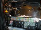
Battery Box Primary186 viewsThis visual is what is next to, behind and under your battery. It is important to note that the negative terminal which is prone to corrosion is in the rear, nearest to everything to maximize damage. The white powder pictured is baking soda. This is carefully used with a damp rag to neutralize any effect of battery acid (hydrochloric acid).
|
|
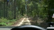
Access road to Pyrocarpa Flora Reserve120 viewsGenerally well formed road - a mixture of decomposed granite and sand in places. Evidence that it is used heavily used by trail bikes but we did not observe any that day.
|
|

Rocky Creek Dam124 viewsOne of two dams that supply most of NE NSW with water.
|
|
Plaque near Rocky Creek Dam129 viewsPlaque honouring Big Scrub Flora Reserve. A few kilometres along on Gibbergunyah Range Road that goes up to headwaters of creeks flowing into Rocky Creek Dam.
This reserve was part of one of the largest single tracts of rainforest in Australia.
|
|
DROPS truck - now that's fun!355 views
|
|
Fuse Panel showing F35P Add A Circuit installed1241 viewsFive amp fuse F35P is located towards the top left in this jpg. The other three Add A Circuit devices are for other items - powering my cell phone base etc.
Note the orientation of the Add A Circuit as this matters. Also one can just see a red tab sticking out from behind the device. The red is the conductor crimp end of a narrow 2.8mm male spade type connector that inserts into one of the "fuse" slots.
|
|

What happened to the Permagrin?113 viewsNoticed that Permaglum had set in, in our group ...
|
|
Philips D2S 85122 C1 Xenon 4300K projector HID bulb962 viewsThis is the 4300K OEM bulb in our HID Xenon projector headlights. People who design illumination systems regard the 4300K colour as a good compromise to provide what is called definition. This is effectively the ability to actually determine what an object being illuminated probably is. The more blue colour bulbs, say 5000K and greater, result in a reduction in the ability to distinguish detail, (regardless of brightness), of the object being illuminated. Effectively, you can see the object but you cannot quite figure out what it is. This is because the more blue frequencies means there are fewer other frequencies of light that allow our eyes to actually discern what an object really is.
The 4300K colour temperature applies to clear air conditions; for rain, dust, snow, fog, etc, then a yellow 2500K colour temperature is preferable. 2500K provides more contrast and there is less back splash of light off the air particles. In blowing snow, this means less sparkle back. Flat top cut off of the light beam, (which is the pattern our projector lights have), is important to reducing back splash - hence you do do not want roof mounted lighting for adverse conditions - as low down as possible is preferable, (which is why fog lights generally sit low.)
|
|
270 viewslooks almost like new. still waiting for a few bits of of plastic that still have not arrived after 8 months. good job they are not mission critical
|
|

looking on to see if i get stuck..suzuki just pulled landy out30 viewsbargrips arn't all that good really. thats my excuse and I'm sticking to it. but managed to get some fun places
|
|
What no barriers64 viewsHolidays in France high up in the Pyrenees we decided to drive some of the mountain passes and get as high as we could. Fantastic roads that really demanded your full attention!
|
|
One slip and that burger is MINE66 views
|
|

Well, it doesn\'t look that bad, does it?57 views
|
|
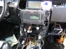
257 viewsSystem testing. Nothing caught fire, which is a success in my book! Just know that the rover gets very angry when all of those control panels are disconnected.
|
|
293 viewsThe rats nest of cabling that needs to be tamed.
|
|
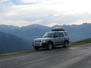
Calendar 2010 My Favorite time of day236 viewsHolidays in France high up in the Pyrenees we decided to drive some of the mountain passes and get as high as we could. Fantastic roads that really demanded your full attention!
|
|

127 viewsThats Me (mine) on the left at McDonalds Kempsy New South Wales. (Next to two older siblings)
|
|
| 485 files on 2 page(s) |
 |
1 |  |
|