| Search results - "unit" |
460 views
|
|
368 views
|
|
420 views
|
|
415 views
|
|
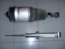
352 views
|
|

Photos don't due the unit justice, the ball can be seen.48 views
|
|
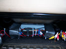
Units in place under pass seat121 views
|
|

2009 Ford ESP Extended Warranty Contract144 views
|
|

Thread upload6 viewsImage uploaded in thread 110148
|
|

playstation 2 slim24 viewsplaystion 2 slim unit
|
|

Old hub unit - Timken19 views
|
|

old hub unit rust - Timken24 views
|
|

Old hub unit rear - Timken17 views
|
|
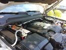
Traxide USI-160 Install515 viewsOverview picture of Traxide USI-160 upgrade install. This was an upgrade from the SC80 which performed flawlessly. The USI-160 had two relays and can deliver more amperage. As a result, the wiring was upgraded to 4/0 Welding Cable (warn) and heat shielding was added. The unit performs flawlessly to support 2 HAM Radios, Fridge, etc. Like me https://www.facebook.com/DifferentialPartsUS
|
|
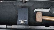
RAW jack2 viewsUnit in place with tools used.
|
|
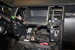
02279 viewsDash center console off and factory head unit out. LR clips suck.
|
|

3 Point Hitch on Series 90152 viewsUsually one sees the Series units with just a conventional field plow hooked to a drawbar hitch, tractor style. This jpg however is the full meal deal - a 3 point hitch, probably off a Fordson tractor, in the long tradition of Ford/Land Rover cooperation.
|
|
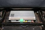
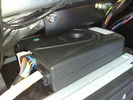
03285 viewsStock amp, underneath passenger front seat. In order to integrate the factory head unit with the V1000 we had to go through the stock amp. This is because of the MOST (fiber optic) connection between the two.
|
|
Thread upload21 viewsImage uploaded in thread 122062
|
|

Thread upload8 viewsImage uploaded in thread 208940
|
|
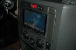
1160 viewsPioneer Nav Unit
|
|
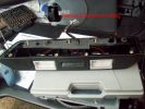
Didn\'t see reference to these anywhere - had to remove them143 views
|
|
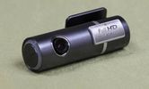
hids4u blackvue hd unit black box153 views
|
|

Black Deposits on Brake Light Switch Plunger2758 viewsThis jpg I got off another forum and is typical of what one will see when one opens up the removed brake light switch. The black powder is residue from arcing of one of the pair of contacts within.
Hopefully the newer switches with the FOMOCO logo moulded into the plastic are improved from the Land Rover logo marked early units, however I doubt it.
The Ford part number is SW-6572 and/or 7E5Z-13480-A as used on the 2006 to 2009 Ford Fusion's and Mercury Milan's; the Land Rover part number is XKB500110. Cost of switch could be about twenty five dollars. A previous LR part number for the switch was XKB500030, so hopefully the newer LR part number, XKB500110, reflects some improvement in reliability.
It is possible that the new switches are better as I installed a replacement 72,000 km, (45,000 miles) later, at 195,000 km (121,000 miles). When I took the removed switch apart to inspect, it was clean inside. There was no black dust - the switch looked like new, hence they must be improved now.
|
|

Build your own Drawer unit116 viewsStep by Step guide to build your own set of drawers.
Instructions by ~Rich~
|
|

Thread upload5 viewsImage uploaded in thread 199019
|
|

Thread upload2 viewsImage uploaded in thread 200758
|
|

Thread upload1 viewsImage uploaded in thread 200758
|
|
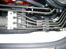
CounterAct Power supply mounted under brake lines.194 viewsThis top view shows where I located the power supply. It is attached with 3M sticky to the black plastic surface that is located under the brake lines.
When the system is operating properly, the red LED pulses about twice per second.
Some users claim they can hear a very slight hum or whine coming from the unit. My unit seems silent.
|
|

Crash Unit34 views
|
|
Thread upload33 viewsImage uploaded in thread 136582
|
|
41 viewsBottom of a Disco 3 Head unit
|
|
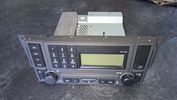
Thread upload55 viewsImage uploaded in new thread
|
|
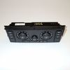
Thread upload4 viewsImage uploaded in new thread
|
|

D4 Gvif Unit Fitting28 viewsHow to fit Gvif unit to a D4 sat nav screen
|
|

419-08 Low and High line radio systems components and operation838 viewsThis 15 page pdf displays the radio components including pinouts for both the low and high line head units and the two Harman Kardon amplifiers including the Logic 7 amp. The steering wheel controls for both the radio and phone system are also outlined along with mention of the Sirius satellite radio feature.
|
|

Thread upload7 viewsImage uploaded in thread 184165
|
|
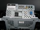
sat nav unit1084 views
|
|
Thread upload5 viewsImage uploaded in new thread
|
|
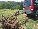
LR3 to plow your garden298 viewsI found this jpg where a current LR owner is using his LR3 for a similar purpose as the original Series units were designed to do - that is serve as a tractor for plowing a field or I suppose a garden.
In this case, I note the hitch is one of those that attach to the factory tow loop, (Rhino Hitch), rather than the factory product that inserts from the bottom and hangs down - (like a plow), but all the time. One of the other jpg's in this album shows the two factory variations plus a third jpg shows a closeup of the Rhino Hitch.
|
|

cutting list for drawer unit13 views
|
|

Location of the unit493 views
|
|
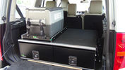
Ironman Drawers and Fridge Slide112 viewsI hate kitsets, over 100 bolts to assemble this unit and lost gallons of sweat, must have read the instructions a hundred times or more but final product does not look so bad. A few bolts hanging out the sides of both slide and drawers that may catch things so time will tell if I made the correct purchase.
Maybe one day I will make some side wings to cover the sides properly.
|
|
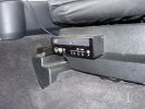
Base unit458 viewsFixed to seat base so it moves with the seat, two power supplies are needed to start up and shut down with the vehicle
|
|
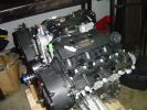
New engine139 viewsReplacement engine, reconditioned unit via Land Rover Australia, circa $6k
|
|
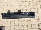
Top view of "Uncle Ray" discrete winch tray, after painting.106 viewsNote that towards the upper right there is a notch in the tray. This is needed for the specific winch's electric solenoid. The winch is a Mile Marker 12,000 lb hydraulic unit.
|
|
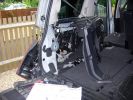
Fitting tow bar storage unit477 views
|
|
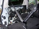
Fitting tow bar storage unit508 views
|
|
Height controller by marcap59975 viewsCentral unit beta test
|
|

Exploded Parts view calling up 6R60/80 and 6HP26/28 variations3113 viewsThis single page jpg exploded parts view indicates some commonality between the Ford and ZF versions of the early and later six speed units. Technically this sheet is for the RWD units as there are variations between plain RWD units, 4WD, and AWD. The transmission in the LR3 is called by ZF to be a 6HP26X and by LR in some publications, the 6HP26
|
|

Gvif unit44 views
|
|

GX107 module with GPS unit and external aerial9 views
|
|

Thread upload13 viewsImage uploaded in thread 65718
|
|

Head Unit5 views
|
|

Thread upload2 viewsImage uploaded in new thread
|
|
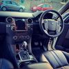
Thread upload2 viewsImage uploaded in thread 189588
|
|
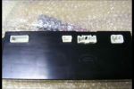
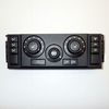
Heater Control Unit Back222 views
|
|
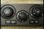
Heater Control Unit Front263 views
|
|

Thread upload6 viewsImage uploaded in thread 187407
|
|

How to swap front panel of HEVAC Unit65 views
|
|
Front of Unit114 views
|
|

Back of unit shows choice of port for best fit94 views
|
|
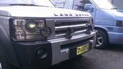
SR40CW lightbar and aset of DS2s on Our Demo Car 334 viewsDiscovery 3 with SR40CW combination lightbar with spot and flood in the same unit and a set of DS2s in place of LR OE spolights
|
|

Completed unit127 viewsReady for frame
|
|

President Johnson II in its current position19 viewsThis CB was installed some years ago and still is at the same location.
However, I'm planning to move it to the head unit area.
As such, I'm looking around to replace my low end head unit with a single DIN radio and the CB on top of it.
|
|

64 viewsAdded a lead coming from the 12V outlet in the front console. That one is activated only when the ignition is set to I. So that's actually what is referred to as accessories in the manual of the radio. The OEM connector for the head unit did not have any similar lead. The yellow is permanent 12V, the red (on the converting OEM 2 ISO) is the accessories 12V.
|
|
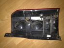
back of NSR light unit20 views
|
|
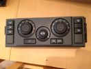
HVAC unit control panel31 views
|
|
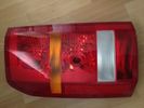
Front of NSR light unit20 views
|
|

Parking unit17 views
|
|

1522 viewsPicture showing two sub bass units and the computer mounted on a board in the newley aquired space.
|
|
Showing the HID ballast units575 views
|
|
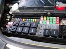
Picture of the engine compartment fuse panel5780 viewsEngine compartment fuse panel located near the battery. This is where F3E, (5 amp), F26E, (20 amp), Fuseable link 10E, (60 amp) and Relay 7E, the now upgraded 70 amp air compressor motor relay, part number YWB500220, (E is for Engine compartment fuse box), are all located. Fuse F35P, (5 amp), is inside the Passenger compartment behind the lower glove box door.
To keep the suspension from going down to the stops when driving, (or parked), it appears that it is only really necessary to remove F26E to depower the exhaust valve and generally keep all the valve block solenoid valves in a closed position trapping whatever air is within the air springs. F3E gets its power thru F26E, so when F26E is removed, the F3E circuit is automatically de-powered. F35P is more interesting in that battery power goes thru the ignition switch and F35P and then into the air suspension control unit. Apparently however, if F26E is removed, removing the F35P is not needed even when the engine is running.
With all fuses still in, if you have a problem, in practice, ideally, the compressor still works and will raise the 3 to an appropriate height. If so, one can then shut the engine off and allow the computers to go to sleep and then you remove the fuse(s). In actual practice, it seems that one need only pull the F26E fuse and can do so with the engine running. All the same, one might consider that the 3 is first a mobile computer, and secondly a 4x4. Computers prefer to go to sleep before the plug is pulled on them, however given that F26E circuit is always alive, then the computer never sleeps. With the fuse(s) pulled, and if you are still up, you can now be a 4x4 instead of a low rider. The whole purpose of the fuse pulling exercise is to depower the one and only system exhaust valve that is physically located within the compressor unit, (to keep it from opening), and secondarily to keep closed the four air spring solenoids within the block valves. This also shuts the air compressor down and stops the air compressor from making air even if the compressor is still good. That is why you initially need the fuse(s) in to allow the compressor to make air if it can.
|
|

Broken Rear Wheel Carrier166 viewsOpposite Lock rear wheel carrier 7 months old, one outback trip. Weld has broken. OL replaced with new improved unit free of charge (has just covered 20000 klm of outback roads without problem)
|
|
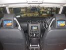
Rear screens running from the Pioneer Avic headunit72 views
|
|

650 viewsLiwa Oasis, United Arab Emirates - the biggest unbroken expanse of sand in the world! [CALENDAR ENTRY]
|
|
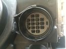
Headlamp unit male pins Xenon B4 cornering light fitting13 views
|
|

scafel pike 3108 viewsJust picked up my new car from Lakeland Land Rover & couldn't resist the opportunity to climb Scafel Pike
|
|

scafel pike 299 viewsJust picked up my new car from Lakeland Land Rover & couldn't resist the opportunity to climb Scafel Pike
|
|

scafel pike 1100 viewsJust picked up my new car from Lakeland Land Rover & couldn't resist the opportunity to climb Scafel Pike
|
|

Helvelyn 117 viewsJust picked up my new car from Lakeland Land Rover & couldn't resist the opportunity to climb Scafel Pike
|
|
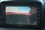
rear-view image60 viewsImage on VMS unit from rear-view camera.
|
|
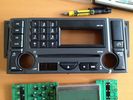
Hk Logic 7 Head Unit Facia replacement9 viewsReplaced facia due to broken buttons
|
|

Front of head unit without facia9 views
|
|

Head unit with front removed16 views
|
|
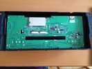
Back view of front panel removed from head unit with facia still attached15 views
|
|

3G dongle for the Android head unit (bring your own SIM)42 views
|
|

Android double-DIN head unit54 views
|
|
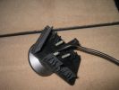
I used the Drive+Play screws supplied with the unit.370 views
|
|
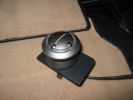
This is the controller unit that I attached to the emergency brake pop-out plate.386 views
|
|

Daytime view of the Drive+Play unit.466 views
|
|
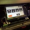
Touch Screen Display Unit13 viewsShowing menu screen shot
|
|
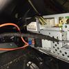
Rear of Touch Screen Display Unit13 viewsShowing connections in place
|
|
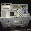
Rear of Touch Screen Display Unit10 viewsShowing details and connections
|
|
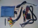
416 views
|
|
JFC50098029 viewsMy current installed unit.
|
|
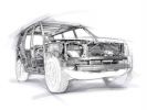
65 views
|
|

Harness that connects inside left rear compartment.445 viewsThis is the harness section that connects behind the left rear interior access panel and exits thru the large grommeted hole to below/behind the left rear tail light.
Note the two rubber grommets on the harness as there is both an interior metal skin and an exterior metal skin behind the left tail light assembly.
The two light grey connectors plug into two existing connectors near the top of the rear left interior access panel. The two darker connectors plug into the second piece of harness.
There is no little separate fuse box either with the NAS spec harness. The fuse box is included with the UK 13 pin dual plug units. If there was a fuse box, it would be on this portion of the harness.
|
|

LR Electric Trailer Brake C2590 Female Connector606 viewsThis female connector, C2590, located up above and near the brake pedal is for the Trailer Electric Brake Controller hookup.
The Black wire in the bottom right is pin #3, the ground. The Blue wire to the left is pin #6, the Trailer Brake Controller output going to the rear trailer socket.
The White #4 wire is the 30 amp fusible link, (Link 6E in the engine compartment junction box), for the Brake Controller 12VDC power feed from the battery. Note that this would make a pretty good power source for CB radios and the like if no electric trailer brakes were required.
Pin #5 is a Green wire from the stop lamp switch, (the control input for the Brake Controller).
This plug is standard on all NAS (LR3) vehicles, but unlikely to be found on the D3 spec units.
|
|

Thread upload18 viewsImage uploaded in new thread
|
|
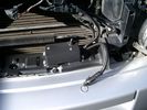
Battery Maintainer switch box and connector 723 viewsThe Hammond box contains a DPDT toggle switch with centre off. The Positive and Negative from each battery feeds to the switch. Depending on the setting of the toggle, (full left, full right,or centre off),the respective batteries connect into the pigtail that can stick out thru the grill when one wishes to connect the charger.
This allows one to charge each battery independently via a suitable battery maintainer. I use a CTEK unit that feeds a maximum of 3.3 amps at 14.4 or 14.7 VDC, depending upon setting. The wiring therefore allows for a slow recharge of either of the batteries separately if either one requires such.
|
|
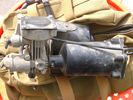
Compressor Air Drier 2044 viewsA view of the air drier - the black round thing to the right of the actual compressor cylinder head.
The general feeling is that the air dryer is responsible for most of the compressor problems now and that replacement of either the assembly or just the beads inside will probably revive one's compressor. In reality, the beads may have for the most part broken down and turned to dust plugging the internal filters. Hence replacement of the complete dryer unit has some merit.
The part number for the dryer assemble complete with the desiccant is VUB504700.
|
|
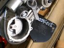
Compressor Con Rod Broken 1753 viewsThe model number of this compressor is RQG500060; the model number of my replacement compressor was LR015303, the unit that was apparently being installed on the D4 vehicles as of Spring 2010. As of Fall 2011, the new replacement part number is LR023964, the same as in the 4's.
Note the number hand written on the black plate. All the compressors seem to have some number hand written on them - hand built I presume, and every unit perhaps evolving a bit differently as LR struggles to build a compressor that will last. I guess Hitachi, (the manufacturer), should be given credit for that.
|
|
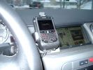
Blackberry Tour mounted on air vent showing default analogue clock 213 viewsA characteristic of the Blackberry is that when charging, the display can default to an analogue clock. Hence when the unit sits in the holder, the phone is being charged and the analogue clock displays. When the phone rings, the clock disappears and the call id displays.
|
|

LR3 Denso Alternator YLE500390 pulley view819 viewsNote the DENSO sticker on the side. Denso calls their nominal 150 amp 12 Volt alternator an SC2 design. SC means Segment Conductor which apparently increase the winding density of the stator coil, hence yielding a physically smaller lighter alternator for a given output. I presume the 2 means the second try at getting it right. A Denso part number is 4280003690 for the alternator, (there are others, as below).
Rotation is clockwise and the 54mm diameter pulley has 6 grooves (PV6x54). Count the pulley grooves on both the one you remove and your new one - some replacement alternators seem to ship with 5 or 7 grooves so you might be swapping pulleys.
A previous LR part number was YLE500190 for the older variation of the newer YLE500390 unit.
An additional part number for a factory rebuilt is Nippon Denso 210-0569 for the petrol V8 alternator. Other Nippon Denso numbers include 104210-3690 and 104210-3691. The Lester number is 11206 which relates to another Denso number of 290-5287. WAI uses 11206N.
From 2006 to 2009, the internal regulator is a Transpo IN6349 and of the B circuit type if it can be said that applies to PWM, (Pulse Width Modulated), regulators.
The "regulator" inside the alternator is therefore really not a regulator in the old sense of the term but instead an instruction receiver from the ECM that translates Pulse Width Modulated (PWM) signals into a form that the alternator understands – digital like signals from the Engine Control Module(ECM) into analogue like signals that the windings understand.
|
|

LR3 Denso Alternator YLE500390 rear view709 viewsThis picture shows the rear of the YLE500390, the Land Rover part number for a newer design alternator utilizing the Transpo IN6349 regulator with the "hidden" cooling fins. Note the visual difference in the rear view of the next file jpg.
If the alternator is a rebuilt, (service exchange unit), but Land Rover supplied, then the part number is LR008860 or similar. (Note that 0 in LR0 is zero.)
Two Denso part numbers exist for the alternator as well, 4280003690 and 4280003691. The rating of the petrol V8 alternator is nominal 12 VDC and 150 amps. In normal day to day operation, they seem to run about 14VDC - usually between 13.9 and 14.1 volts at the OBD port.
For the petrol V6, the LR service exchange number is LR008862, and the 2.7TDV6 is LR008861.
The bridge rectifier within the alternator is a 12 diode avalanche type, 117mm diameter, as used in Nippondenso 120 to 160 amp alternators with the Hair Pin stator. It is similar to a Transpo INR421 which is rated for 120 to 150 amp alternators. That is probably our primary problem - the rectifier is just too light. Alternate part numbers for the bridge rectifier are Cargo 237607, Mobiltron RM-29 and AS ARC6021.
Re the B+ stud, the INR421 calls it up as an M8 x 1.25 x 30 mm long course threaded stud; some say 34 mm but that may be longer than desirable.
|
|
![Filename=LR3_Radio_Removal[1].pdf
Filesize=190KB
Dimensions=320x240
Date added=04.Feb 2014 LR3_Radio_Removal[1].pdf](images/thumb_pdf.jpg)
Radio Removal from Radio Stack571 viewsThis shows how to remove the radio from the stack. Basically you remove the H surround first and then at least loosen all the Torx 20 screws left and right sides from the top down starting at the narrow unit that the four way flasher/locking buttons are mounted on.
The units kind of interlock, hence some movement of each is required to remove the radio by itself. I find it best to take out the four way flasher/locking buttons assembly first as that allows access to the fibre optic cable connector into the back of the radio head without too much tugging.
|
|

MMTracker on a Dealer Fit Pioneer Sat Nav Unit33 views
|
|
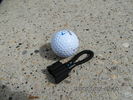
MOST fiber optic loop tool469 viewsThe looping tool in the jpg uses the Land Rover type plastic fiber optic cable with both ends feeding back into a female fiber optic connector that mates with the male fiber optic connectors on the Land Rover system.
The purpose of the loop is to allow one to disconnect MOST connected items such the BlueTooth module or the HK amplifier but allow the MOST system to still transmit signal from the head unit as the circuit would remain closed and hence complete. Of course with the Bluetooth module disconnected, there would be no Bluetooth available, however the radio and NAV would still function.
The looping tool allows one to troubleshoot the system by removing one component at at time from the MOST loop. In other words, what might appear to be a radio problem could be a Bluetooth problem - that sort of thing.
|
|
286 views
|
|
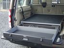
TL1 Secure Storage Systems64 views
|
|
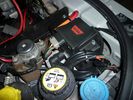
warn winch controller installation613 viewsremotely installed due to space limitations, and to keep the unit dry. Left Hand Drive, fitted in engine bay near washer fluid fill for reference point.
|
|
warn winch controller installation544 viewsremotely installed due to space limitations, and to keep the unit dry. Left Hand Drive, fitted in engine bay near washer fluid fill for reference point.
|
|
warn winch controller installation568 viewsLeft Hand Drive, fitted in engine bay near washer fluid fill for reference point.Remote control unit fitted on the box. Remotely installed due to space limitations, and to keep the unit dry.
https://www.facebook.com/DifferentialPartsUS
|
|
Traxide SC80-LR mounted568 viewsAnother view of the mounted unit.
|
|
The oily bits. PTO unit on back of transfer box. Exhaust had to be \'modified\' to fit.161 views
|
|
Thread upload27 viewsImage uploaded in new thread
|
|
4x4 info Android1 views4x4 info provided by Android unit AC8667L
https://es.aliexpress.com/item/1005003703556182.html?spm=a2g0o.order_list.order_list_main.16.5949194ddA7E9L&gatewayAdapt=glo2esp
|
|
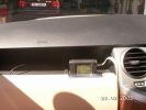
236 viewsVehicle Unit Display held on with Velcro, easily removable
|
|
241 viewsTrailer Display unit lives here when not in use. Note the Genisyz split charging display also lives here.
|
|
215 viewsTrailer Display unit when in use - Cable long enough to position anywhere suitable
|
|
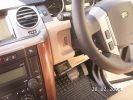
224 viewsUnit accessible to change from on-road to off-road mode
|
|
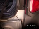
233 viewsRouting of the Trailer unit antennae through the rear door rubber & behind the bumper on the outside of the vehicle
|
|
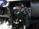
278 viewsA mess of cables. You can see the HD Radio antenna adapter coming out into the slot for the IHU. You can also see, if you look very closely, the original diversity antenna connector plugged into another adapter to go down to the HD radio unit.
|
|

Thread upload6 viewsImage uploaded in thread 161773
|
|
Output from DVD player - Input to Interface Unit326 views
|
|
Output from DVD player - Input to Interface Unit - and output from interface to LCD337 viewsAll connected up
|
|
interface unit sat on dvd - cables pulled under seat frame409 views
|
|
Interface unit hidden at side of the dvd player435 views
|
|
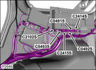
remove metal clips from floor panel and reinstall on to the plastic trim296 viewsIf you leave the clips in place and try to force the trim back in the clips are knocked through the floor unit and it takes an hour to get them out!!
|
|
Audio amplifier & DAB unit & Door lock system106 views
|
|
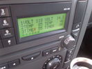
Voltage Display Page Radio Head Unit 118 14.2840 viewsThis shows the voltage/temperature/timer display page within the 6CD-465 radio head. There is a second file within this album, a doc file, that outlines the procedure to access the diagnostics.
The 14.1 volts number was the approximate vehicle system voltage with the engine running; the 118 number infers 11.8 volts which is the low power infotainment system shutdown cutoff voltage. The factory default setting is 135 or about 13.5 volts. By holding the keypad 1 button down, the 3 digit volts numbers will decrease 001 at a time until the keypad 1 button is released. Decreasing the number from 135 to some lower number should increase the time the system will remain on with the engine off.
The TEMP numbers refer to Fuel Burning Heater, (FBH), temperature values. 85 is apparently a high limit and 46 was the number when the jpg was taken. This number varies and given that there is no diesel fueled FBH in our NAS petrol engine vehicles, what the value refers to is unclear. The TIMER numbers also relate to the diesel fuel burning engine heater and perhaps make more sense being 00.
|
|
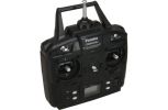
rc unit105 views
|
|

Transpo Regulator IN6349 Pin Assignment716 viewsThis pdf shows the Land Rover and Ford pin naming for the 3 pins in the receptacle of the Transpo IN6349 regulator that accepts PWM signals. This jpg is as if you are looking into the receptacle located on the alternator.
Also provided are the Transpo pin names that are in common use and that some may be more familiar with plus some comments re testing.
The IN6349 regulator is used in the newer LR part # YLE500390 alternator. For the older YLE500190 alternator, the regulator is a Regitar VRH2005-142 unit that is shaped a bit different than the newer IN6349 regulator. Externally, the main difference is that no shiny fins are visible on the rear of the newer YLE500390 alternator. The pin naming and numbering is the same for both and both alternators are interchangeable.
|
|

View with camera attached to reverse cam pins on back of touchscreen unit (not working as it should?)68 views
|
|

Rosen A10 Manufacturer Installation Manual763 viewsThis is a 30 page pdf from Rosen that explains how to install the A10 unit. It is Generic in nature and hence carries detail not found in the LR specific install instructions. It also uses words and pictures instead of just pictures, hence can be a bit easier to figure out, particularily if you wish to take advantages of some of the hidden features not described in the LR material.
One of these features is how to hook up to a headrest display or I suppose even to the NAV in front.
|
|

Group 2 - Lead by me!208 viewsHaving finally got free of the Roych we stopped for a photo opportunity - like you do!
|
|
FFRR Nokia phone module29 views
|
|
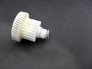
The faulty unit (secondary gear / torque clutch)376 viewsShowing the inadequate circlip retaining land, ripped iopen by the normal spring tension. Should never have been made of plastic...
|
|
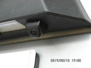
Tailgate Camera located above license plate.598 viewsThis aftermarket camera is mounted on my 2005 LR3 in almost the same location as the factory cameras. The factory units are mounted somewhat more forward closer to the metal of the tail gate and I could have done the same as well.
Note that the camera above is aimed a bit towards the centreline of the vehicle per the factory install.
|
|
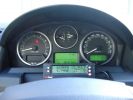
ScanGauge II on steering column of LR3800 viewsMAP is Manifold Absolute Pressure, what I call Vacuum.
The volts is I think the battery charging voltage as it moves around from about 12.4 when shut down to 13.5 when the batteries seems charged; 14.9 is about as high as I have seen it display.
You also have RPM, speed in MPH or KPH, coolant temperature and a bunch of other readings including sort of instantaneous fuel in a variety of units.
Also under some conditions, the ScanGauge will reset the MIL light as well. The background colour of the display can be changed to many different colours. I have it set to match the LR green.
|
|

ScanGauge II Manual 341 viewsThese are the setup instructions etc for the ScanGauge II version 5.1 There are newer versions that can be downloaded from the website www.scangauge.com as the software is subject to update; also the ScanGauge unit you purchase can later be sent in for updates as you might wish.
|
|

Italian Maintenance Check Sheet135 viewsJLR 11 82 14_6E (6)
SCHEDA DI MANUTENZIONE (TUTTI I MODELLI REGNO UNITO ED EUROPA)
|
|
Loft Unit31 views
|
|
Power Unit27 views
|
|
reman unit1129 viewshttps://www.facebook.com/DifferentialPartsUS
|
|
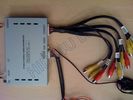
AV Inputs and Outputs GVIF Interface Unit344 views
|
|
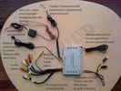
How to connect the GVIF to the car467 views
|
|
281 views
|
|
179 views
|
|
193 views
|
|

38 viewsBottom of a pre 2010 Range Rover Sport Head unit
|
|
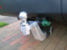
LR "plough" with 150mm high-rise alloy tongue.171 viewsI fitted this 150mm high-rise tongue to the LR towing hitch. It's a solid aluminium alloy unit called a "Stinger" or "Alumnistinger". Made in the US and available in Australia through a distributor in Brisbane Qld.
|
|

Superinjunction85 viewsBefore Ryan Giggs was exposed as the two faced, nice as pie in public yet screwing any that moves behind closed doors hypocrite he is it was public knowledge that the woman in the story was some slapper from Big Brother but the footballer could not be named. Here we see TNT magazine's top story about her saying the footballer can't be named. Directly underneath is a link to a "related story" was a link to "Ryan Giggs, wife and kids celebrate Manchester United victory"
|
|

Tekonsha P3 Brake Controller 90195 to Ford 3035-P wiring adapter plug311 viewsThis two page pdf is the general instruction for hooking up the Tekonsha part number 3035-P adapter cable between a Tekonsha P3 controller and the existing Land Rover/Ford plug, (called C2590 in the Land Rover wiring diagrams), that is hidden above the brake pedal.
The "Ford" plug, (C2590), is grey and is stuffed up above the brake pedal arm.
Mount the P3 controller appropriately and then connect one end of the custom cable to the P3 and the other to the "hidden" plug.
You will now have power for your trailer electric brakes in the round socket at the rear of your LR3; also no computer update from the Land Rover T4 unit is required. For once, it is plug and play.
If however, your trailer has LED tail lights, you may have trouble with the flashing of the trailer signal lights or non recognition by the 3 that a trailer is connected. As such, the little green trailer signal will not illuminate when a trailer is connected and the signal lights are used. This can affect the shifting of the transmission and much to your annoyance, the backup sensors will still be functioning rather than being auto disabled.
|
|

Tekonsha P3 Electric Trailer Brake Controller model 90195291 viewsOne model of electric brake controller that is commonly used on the LR3 is the Tekonsha P3 unit, model number 90195. It mates up to the LR3 with a custom "Ford" adapter cable, Tekonsha part number 3035P. No wire cutting or splicing is necessary - just mount unit and plug adapter cable in.
|
|
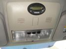
141 viewsGreat care should be taken when securing the timer to the light unit. Overtighten the screw and you will damage the LCD display of the timer.
|
|

TransK9/B12 in Discovery 4 with Secure Storage Unit41 views
|
|

Thread upload34 viewsImage uploaded in thread 196132
|
|

Thread upload34 viewsImage uploaded in thread 196132
|
|

Thread upload33 viewsImage uploaded in thread 196132
|
|

Thread upload8 viewsImage uploaded in new thread
|
|

Thread upload16 viewsImage uploaded in thread 134042
|
|
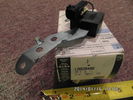
Radio Noise Filter Transmission Electronic Control Unit915 viewsThe jpg shows part number LR020488, a noise suppression capacitor located underneath on a bracket on the right side of the transmission forward of the selector shaft lever. The suppressor is connected to the transmission wiring harness and prevents solenoid operating noise affecting the audio system.
Failure of the capacitor is most often discovered as a result of either black smoke from below and or the blowing of 10 amp fuse F30E located in the engine compartment fuse box. This fuse protects the power circuit to the Transmission Engine Control Unit. When the fuse blows, the engine will still run however you have no gears, hence movement of the 3 is inhibited.
Anything over eight years in service is considered good capacitor life. If the capacitor does fail and fuse 30 blows, a quick fix is just to disconnect the capacitor and replace the fuse.
The capacitor might be missed by the DOT/FCC but the 3 does not seem to mind. With the filter disconnected, solenoid noise might be heard on some radio stations but at least the 3 would be in motion.
|
|
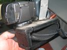
UHF Head Installation104 viewsThe unit is made from 16 mm craftboard. Screwed and glued together. A tight fit. A little silastic to help keep it in position.
|
|

United Kingdom25 views
|
|

Thread upload2 viewsImage uploaded in new thread
|
|

Wire in roof, behind light unit43 viewsAny ideas?
|
|

ZF 6HP26 and 6HP28 Comparison plus oil pan and filter replacement options963 viewsThis is a 66 page ZF produced pdf that provides comparisons between the various ZF transmissions; also instructions regarding maintenance of the Mechatronic unit, the round seal; the various metal and plastic pans available as well as tips regarding changing the oil.
This ZF pdf has a number of colour pictures and part numbers within as well.
|
|

Electrical Connector Sleeve Replacement ZF 6HP26973 viewsThis 3 page pdf with pictures shows how to replace the sleeve that holds the multipin electrical connector that passes thru the transmission body to the Mechatronic unit.
The install of the sleeve is more difficult than the removal in that one must not rotate the sleeve as damage to the internal pins can result. The pan must be first removed to both remove and install the sleeve.
|
|
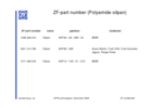
ZF Plastic Pan / Filter part numbers852 viewsZF, not Land Rover, part numbers for the various types of plastic pan depending upon vehicle manufacturer. The BMW pan is apparently different from the Land Rover pan even though the transmissions are 6HP26 units. No wonder each manufacturer has his own oil - maybe it is different as well. What I find interesting is the mention of Ford Australia and Ford USA separately rather than just Ford.
|
|

Gear Sump Sequence 96 views
|
|

Troubleshooting pdf re Mechatronic unit on 6HP26 ZF Automatic 2145 viewsThis 21 page pdf shows possible problems within the Mechatronic unit of the ZF 6HP26 six speed automatic. On page 19/21 is a drawing showing how all the various control circuits interface with the vehicle.
Of particular interest were comments with regards to fine metal contamination of various electrical contacts. This is probably why a mere oil change can improve the operation of the transmission - reduced conductivity of the oil.
|
|

Mechatronic Replacement Hints plus drains for steel and plastic pans1111 viewsThis 22 page pdf shows colour views of the Mechatronic unit as well as good illustrations of the drain and fill ports in both the plastic, page 17, and steel pans, page 18.
Page 8 details the replacement of the sealing sleeve where the electric wire feed thru the case into the Mechatronic unit. The seal is normally replaced when a new pan is installed as the seal is a known leakage point.
|
|
|
|
|
|