| Search results - "upper" |

Floor console upper panel removal213 views
|
|
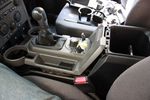
90 viewsLifted floor console upper panel to enable cubby box removal
|
|
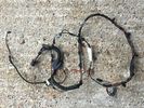
Upper Tailgate Loom (no Camera) BH22-14A583-AA Pic39 views
|
|
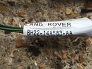
Upper Tailgate Loom (no Camera) BH22-14A583-AA Pic26 views
|
|
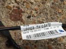
Upper Tailgate Loom (no Camera) BH22-14A583-AA7 viewsOne Pin loose on grey plug
|
|
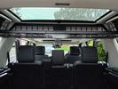
Upper tray20 views
|
|
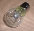
Land Rover Stop Tail Light dual filament bulb nominal 12 volt 21 / 5 watt filaments1427 viewsThis is the Land Rover part number 264590 dual filament bulb, (P21/5), that inserts into the upper two tail lamp receptacles. In the upper one, both filaments function, in the lower one, only the 5 watt tail light filament functions.
I regard it as not a good practice to routinely switch bulbs when the tail light filament, (5 watt), burns out on the lower bulb. The broken filament can jiggle over onto the brake light filament, (21 watt), and short the circuit to ground or something else not predicable.
There are also arguments to say that quality control is better on the Land Rover marketed bulbs than say far east sourced bulbs. Filament construction, and hence resistance can vary and mislead the current sensing circuits monitoring the signal light systems. Also when the bulbs are properly installed, all filaments should be standing vertically and not at any slope.
These are the sort of obscure circumstances that can lead to false trouble messages on the display, dropping to the stops, and subsequent concerns - all over a tail/signal light bulb.
For example, the filament life of both the tail light and the brake light filaments in the P21/5 bulb is significantly less than the USA common 1157 dual filament bulb, (1000/250 vs 5000/1200 hours); brightness in the P21/5 is a bit more, (3cp/35cp vs 3cp/32cp where cp is candle power), but current consumption is oddly less, (0.44a/1.86a vs 0.59a/2.10a where a is amps). It is the quest for efficiency vs maintenance trade off.
|
|
Thread upload3 viewsImage uploaded in new thread
|
|

D4/LR4 501-12-floor console upper panel install instructions / german language72 viewsD4/LR4 501-12-floor console upper panel install instructions / german language
|
|

Land Rover Aerial Fin images for both Glass and Metal Roof Disco3 / LR3864 viewsAs well as the two different fins, this pdf also shows the plastic blanking plate for glass roof vehicles where no fin is installed.
The glass roof fin is secured by two security screws from the top into a plastic frangible glue on gasket. The hope is that when struck, the fin will shear off and not crack the glass roof. Re the metal roof design, the fin is secured from underneath via two nuts.
The pdf also shows the various electrical bits related to the antennas. In the UK, the fin would house not only a cell phone antenna but the TV and satellite radio antenna electronics as well; in the States, the Sirius sat radio antenna and a G type cell phone antenna if the phone kit was installed would reside within the fin. The SAT NAV GPS antenna is located within the High Mount Brake Light plastic mounted to the upper rear hatch.
|
|

Fin cell phone aerial drawing190 viewsThe factory aerial for the factory NAV / GPS on my 2005 HSE is within the high mounted stop light lens at the top of the upper hatch door. I do not have the factory installed phone kit, and as such, do not have the fin installed; instead there is just a plastic blanking insert to fill the cell phone aerial wiring hole in the metal portion of the roof; hence this requirement for an "external" cell antenna. For those that do have the fin on their glass roof, the fin is screwed on to a glued on plastic gasket, (sort of), and not bolted thru as per the metal roof 3's.
|
|
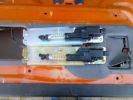
upper tailgate actuators146 views
|
|
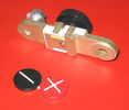
Battery Disconnect side post with + & - caps under view744 viewsThe upper and lower pieces of metal are clamped together but electrically seperate from each other. The connection between the two pieces is via the threaded part attached to the knob. When the knob is turned tight, current will flow between the two sections of metal.
|
|
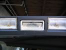
upper tailgate switch without rubber121 views
|
|
Thread upload17 viewsImage uploaded in new thread
|
|

Interior Trim269 views
|
|
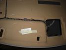
Hidden Mic Connector142 viewsMic connector on upper side of head lining just above & behind sun visor
|
|

Cam cable to upper tailgate31 views
|
|

Thread upload7 viewsImage uploaded in thread 199265
|
|

Thread upload5 viewsImage uploaded in thread 126959
|
|
Thread upload24 viewsImage uploaded in thread 163428
|
|
Sump guard, upper limit409 views
|
|

upper aux. belt roller39 views
|
|

aux belt upper roller - cap removed64 views
|
|

Upper aux belt roller removed50 views
|
|
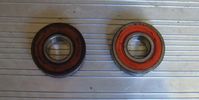
lower roller bearing RHS, upper on LHS49 views
|
|
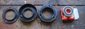
upper aux belt roller for re-assembly54 views
|
|
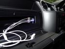
iPod connectors17 viewsAux video and Audio inputs (for nav screen) and usb charge point in upper glovebox
|
|
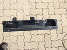
Top view of "Uncle Ray" discrete winch tray, after painting.107 viewsNote that towards the upper right there is a notch in the tray. This is needed for the specific winch's electric solenoid. The winch is a Mile Marker 12,000 lb hydraulic unit.
|
|
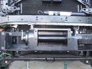
Close-up front view of partially-installed winch121 viewsNote that the sheet-metal flange just above the winch had to be notched to allow winch controller to be actuated. Also this same bracket had to be bent upwards to allow the winch hydraulic:electic solenoid to fit without rubbing. The nut on the upper-left bolt (the one with a very faint circle around it) stripped on re-installation, so the tray and winch pulling load is held only by the threads on 7 bolts....
|
|

G4 on Copper Snout, Upper Coquet Valley, Cheviots, Northumberland - GToN114 viewswww.gton.co.uk
|
|

Floor Console Upper Panel102 views
|
|

Interior Trim471 views
|
|

Floor Console Upper Panel65 views
|
|

20 views
|
|
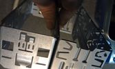
38 viewsWhen adding two single DIN supports together, you get quite a gap at the front.
This gap was way too much in my case, as it turned out that both supports started to bend when putting them both in the facia. Not that good, so I decided to cut off the upper part of the lower DIN support.
|
|
![Filename=IMG00118-20100131-1456[1].jpg
Filesize=40KB
Dimensions=614x461
Date added=31.Jan 2010 IMG00118-20100131-1456[1].jpg](albums/userpics/12824/thumb_IMG00118-20100131-1456%5B1%5D.jpg)
Upper Tailgate Latch mechanism142 views
|
|
![Filename=IMG00119-20100131-1456[1].jpg
Filesize=57KB
Dimensions=717x538
Date added=31.Jan 2010 IMG00119-20100131-1456[1].jpg](albums/userpics/12824/thumb_IMG00119-20100131-1456%5B1%5D.jpg)
Upper Tailgate Latch mechanism156 views
|
|

Mantec Upper Load Lugga10 views
|
|

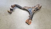
upper suspension arm ball joint76 views
|
|

Img 4103 viewsUpper glove box removed. Here you can see the power supply for the lower glove box light. Simply use this as your power supply for the new upper light.
|
|

LED light - cable through boot into upper tailgate104 views
|
|

Part numbers for JAE connectors for the upper hatch switch. 382 viewsThis lists the JAE and Digi-Key part numbers for the electrical connectors for the hatch switch.
I contacted Japan Aviation Electronics and they directed me to Digi-Key in the USA who sell odd lots of the JAE product, odd lots meaning two pins and one connector if that is all you wish.
|
|

JAE connectors for the upper hatch switch and FAKRA connectors for the Sat NAV.539 viewsThis jpg shows some catalog pages listing the MX19 connectors used on the upper hatch switch.
Also shown are the FAKRA connectors that are used on the rear of the Sat NAV.
|
|

Replacement switch from RRS installed on LR3864 viewsThe switch shown is LR part number YUZ500020, the upper rear hatch release switch that is found on the Range Rover Sport.
The switch body is the same switch as on the LR3 except that there is no wiring disconnect on the LR3. Hence when the switch corrodes and requires replacement, the LR solution is to purchase a new handle and license plate light assembly. I instead cut off the old switch and installed a JAE mating connector to the existing wiring and hence just plugged the RRS switch in.
The replacement RRS switch snaps into the same rectangular space in the same manner as the removed LR3 switch, the difference is the JAE male wiring connector.
|
|
![Filename=kit615-rear-upper-arms-kit-discovery-3-4-lr051622-lr051623-all-fittings-103244-p[ekm]270x194[ekm].jpg
Filesize=16KB
Dimensions=270x194
Date added=13.Jun 2019 kit615-rear-upper-arms-kit-discovery-3-4-lr051622-lr051623-all-fittings-103244-p[ekm]270x194[ekm].jpg](albums/userpics/33392/thumb_kit615-rear-upper-arms-kit-discovery-3-4-lr051622-lr051623-all-fittings-103244-p%5Bekm%5D270x194%5Bekm%5D.jpg)
Thread upload9 viewsImage uploaded in new thread
|
|

Thread upload5 viewsImage uploaded in new thread
|
|
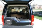
200 views
|
|

59 views
|
|

Upper tailgate lock / cable31 views
|
|
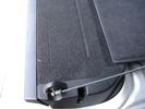
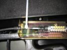
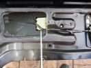
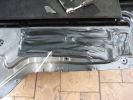
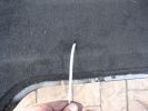
Flexible wire rope fishing leader 0.032" diameter exiting carpet 1949 viewsThis is all you see of the completed mod.
The short little angled "line" about an inch long that looks like a piece of debris and is located a few inches "above" the support cable is actually the wire rope release cable exiting from under the carpeted lift gate cover.
I drilled a very small hole in the carpet and pushed the 0.032" diameter release wire thru and then slipped the loose end under the black plastic.
To release with the lift gate etc closed, from the inside, just pull the loose end free from under the black plastic and gently pull wire about 5mm, (1/4"), and the upper door catch should release. You will have to manually push the upper door out wards to actually effect opening, but you will already be inside the rear cargo area so that part is easy to do.
The assumption is that the lower door latch still works electrically and hence, the lower lift gate half will open as normal by pressing the usual button on the top left of the lower door half.
|
|
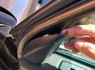
Thread upload6 viewsImage uploaded in thread 128326
|
|

LTB00296 - Technical Bulletin - Upper Glove Compartment Rattle77 views
|
|
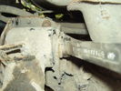
rear upper rear bush299 views
|
|

Pegasus 2133 viewsDamage caused to our Bailey Pegasus 514 by the front towing protector upper securing sucker
|
|

Pegasus 1133 viewsDamage caused to our Bailey Pegasus 514 by the front towing protector upper securing sucker
|
|

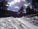
Killington, VT32 viewsUpper driveway pulled back
|
|
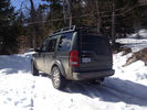
Killington, VT28 viewsdriveway upper top
|
|
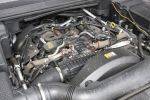
Killington, VT37 viewsParked on upper driveway, the driveway was covered with 6 inches of snow and the incline was at least 30 degrees and the LR3 made it up with no problems.
|
|
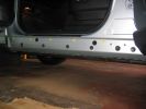
EGR Pipe Clips831 viewsRemove the 2 circled clips to disconnect upper ends of EGR pipes from the stub pipes fitted to the EGR butterfly valve housing.
|
|

Refurb Upper Front Wishbone 163 views
|
|

Refurb Upper Front Wishbone62 views
|
|

Refurb Upper Front Wishbone 268 views
|
|

25 viewsshowing the fixed tensioner on the upper right of the engine
|
|
Front N/S Upper Mounting Holes172 views
|
|
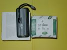
Upper Hatch Release Switch LR Part Number YUZ500020676 viewsThis is the Range Rover Sport switch, Land Rover part number YUZ500020, as it comes out of the box. Note the JAE, (Japanese Aviation Electronics), male wiring connector installed on the end of the power lead.
The rubber cover of the switch is sealed to the plastic body of the switch whereas in the previous switch design, there was no sealing. Also the replaced switch was hard wired into the same harness as the license plate lights - no JAE connector in other words.
|
|
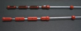
TDv6 Oil dip stick280 viewsPhoto shows oil level on rear stick (cleaned front stick). Note that diesel oil when fresh may not be black like the sample shown (car had travelled 5 000km on delivery oil). You can see small indentations in both sticks. This is where I observe the current oil level. Note also the two arrows at either end of the red plastic indicators showing lower and upper limits (I do not know what the red ball is for however - it just may be a guide.)
|
|
216 views
|
|
197 views
|
|
210 views
|
|
204 views
|
|
188 views
|
|
190 views
|
|
185 views
|
|
209 views
|
|
Thread upload3 viewsImage uploaded in thread 199620
|
|

Thread upload1 viewsImage uploaded in new thread
|
|

Thread upload0 viewsImage uploaded in new thread
|
|
Thread upload4 viewsImage uploaded in new thread
|
|

215 views
|
|
Thread upload3 viewsImage uploaded in thread 195246
|
|

67 views
|
|
Thread upload5 viewsImage uploaded in thread 52130
|
|

Thread upload3 viewsImage uploaded in thread 64970
|
|

upper tailgate5 views
|
|

Thread upload8 viewsImage uploaded in new thread
|
|
|
|
|
|