| Search results - "valve" |
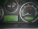
EGR blanked - new mpg!68 viewsAttained 30+mpg after EGR valves blanked by TFC
|
|
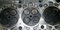
No damage to valves18 views
|
|
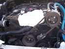
221 viewsRemove the air intake shuttle cut off valve, covering hole with rag
|
|

Timed Climate Coolant Valve54 views
|
|
27 views17" alloy
|
|
Compressor Valve Bracket910 views
|
|
Vacuum pipe + valve LHD 14 views
|
|
Oil change valve22 views
|
|
6" Ball Float Valve207 views
|
|

Oil change valve 221 viewsStahlbus M14x 1.5mm
|
|
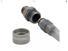
Oil change valve 316 viewsM14x 1.5mm
|
|

Connector: C2101104 viewsDescription: Rear control valve
Location: Below LH rear wheel arch
Part No.: YPC800230
Colour: BLACK
Cavities: 6WY
|
|
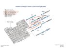
Thread upload3 viewsImage uploaded in thread 179988
|
|
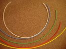
6mm Heat Shrink colours 362 viewsI decided to colour code the tubing so I used 6mm electrical heat shrink.
As there is no apparent colour coding re the 3, I tried to emulate the P38 coding; #1 LR red, #2 RR blue, #3 LF yellow, and #4 RF green. This was not doable as both left side air springs have green coloured tubing coming off the top of the front and rear air springs. I therefore arbitrarily chose the Left Rear to be red; Left Front green; Right Front yellow; Right Rear blue; and for the air compressor supply line, White coloured heat shrink. Since two new lines tie into each air spring line, I made the line between the air spring and the FASKIT, a single solid colour, and the line from the FASKIT to the valve block, White, plus the related appropriate solid colour.
|
|
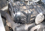
Airbox to EGR Butterfly Valve Housing Leak97 views
|
|
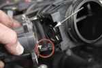
Removing the EGR Butterfly Valve Actuator1538 viewsRemove the 4 TORX screws to remove the actuator. The small black link (circled) connects the actuator drive arm with the butterfly valve spindle (arrowed). The spindle can now be very carefully levered out using a screwdriver inserted beneath the arrowed bit in the photo. A bit scary to do as it takes a fair bit of pressure before the spindle will free itself from the butterfly. Once it starts moving though, it gets easier to pull out.
|
|

315 views
|
|
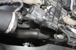
Air Box Removed1058 viewsView showing air box removed from front of EGR butterfly valve housing
|
|

Thread upload5 viewsImage uploaded in thread 185498
|
|
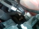
Breather Cap Installed2006 viewsThe black L shaped tube is is the Gore manufactured, (the Gore-Tex people), LR4 Breather Valve installed in an LR3. Naturally the installation looks similar to what one sees on an LR4 or RRS as the Gore breather valve is now OEM for new production.
The part number of this upgraded front differential breather valve is LR019450 and costs about thirty dollars.
|
|
Thread upload15 viewsImage uploaded in thread 55986
|
|
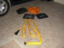
The kit as supplied180 viewsContains carry bag, 2 protector mats, exhaust jack and 7m reinfoced woven hose with bayonet connector to bag (inc non-return valve) and rubber cone for exhaust fitting
|
|
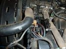
compresor_shut_off_valve_223 views
|
|

200 views
|
|

Cooling system hoses - 4.4L petrol V81109 viewsThese are the cooling system hoses on the 4.4L petrol V8. The little odd shaped bleeder hose, (LR006158), shown in the top right hand corner can give problems. There is a plastic tee with a threaded air bleeder outlet located in the middle of the hose. The plastic tee can or will fail due to I guess heat distress.
A BIC pen can serve as a field fix, however for your parts kit, a nominal 3/8" ID hose size brass hose barb inline connector plus a couple of hose clamps is suggested. Better yet is a threaded hose barb brass coupling or a tee and bleeder valve to allow bleeding of the line. Land Rover now makes the plastic bleeder valve that breaks available as a separate part, # LR027661, where 0 is a zero. As such, one can now purchase that part only for addition to your field fix parts kit.
|
|
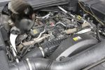
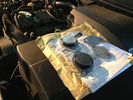
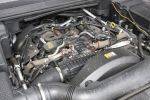
Engine Cover Removed901 viewsView of the engine before blanking off the EGRs. The inset sort of shows one of the EGR valve/pipe flange securing bolts. The EGR valves are not easy to get at!
|
|
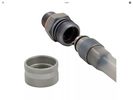
Oil change valve 420 viewsM14x 1.5mm
|
|

D4 Coolant FBH Valve26 views
|
|

Thread upload2 viewsImage uploaded in thread 125790
|
|

27 views
|
|

Thread upload0 viewsImage uploaded in thread 125790
|
|
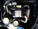
D4 FBH with heater matrix valve59 views
|
|

96 viewsEnterprise D4 courtesy of EGR valve total failure and LRA.
|
|

46 viewsEnterprise D4 courtesy of EGR valve total failure and LRA.
|
|

57 viewsEnterprise D4 courtesy of EGR valve total failure and LRA.
|
|

50 viewsEnterprise D4 courtesy of EGR valve total failure and LRA.
|
|

46 viewsEnterprise D4 courtesy of EGR valve total failure and LRA.
|
|
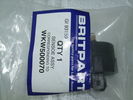
Fuel filter drain valve/water sensor33 views
|
|
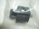
Fuel filter drain valve/water sensor30 views
|
|
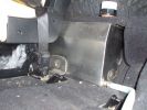
Left hand side of internal 40 Litre water tank161 viewsView from floor looking towards tank. Top white cover is 50mm plastic pipe cap. It protects the tank vent valve. Dispensing hose is at lower corner of tank
|
|

J Moore EGR137 views
|
|
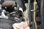
EGR Valve/Pipe Flange895 viewsThe bolts in the inset are the ones to be removed. Note the rag stuffed down beside the EGR to prevent dropped bolts or gaskets disappearing for ever. Don\'t forget to take the rag out if you don\'t want your D3 to go up in flames next time you use it!
|
|

Thread upload9 viewsImage uploaded in thread 137104
|
|
Thread upload13 viewsImage uploaded in thread 143895
|
|

South African Disco 3 2007 model (VIN 7A) EGR valve Right hand side.46 viewsIt is still an EU3 spec vehicle, so the EGRs can be blanked off successfully.
|
|

Thread upload1 viewsImage uploaded in thread 198799
|
|

Fuel Purge Valve and other hoses.846 viewsThis 6 page pdf shows the Fuel Purge Valve and associated hoses and describes how it is supposed to work. There are lots of good drawings of the fuel system. It is more complicated than one might think.
|
|
Thread upload4 viewsImage uploaded in thread 175852
|
|
Thread upload21 viewsImage uploaded in thread 123657
|
|
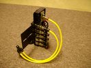
FASKIT on end view 864 viewsEnd and rear view of the FASKIT. Yellow lines are as shipped for hooking to the air supply; one line to valve/filler and other is to gauge. I will modify the arrangement to delete one of the yellow lines such that gauge line plugs into where the second yellow line is right now,(will be only one yellow tube), and then the air source line will plug into the port controlled by the valve, (hidden in this view but visible in other view). When white valve is in the ON position, gauge will read air source pressure, and be available to supply air to any of the selected four air springs. When valve is closed, the gauge will show individual air pressure in each of the air springs when a jumper is run between the gauge Schrader valve and the appropriate air spring Schrader valve.
|
|
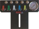
FASKIT air panel unmounted843 viewsThis is the manual air valve panel that is mounted in the "empty" space where the FBH normally resides. The gauge reads to a maximum of 25 Bar. The air tank relief valve is set just over 16.5 Bar (240 psig); the front air springs run maybe 9 Bar, (130 psig) and the rear, somewhat less, perhaps between 5 and 8 Bar. (70 to 115 psig). Max theoretical air spring pressure at full compression due to a big bump and full gross is approximately 27 Bar (390 psig).
|
|

Thread upload18 viewsImage uploaded in thread 200211
|
|

6 views
|
|
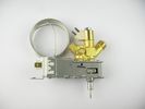
gas valve fridge5 views
|
|

TDV6 Valves47 views
|
|
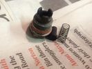
Valve Kit26 views
|
|

Valve Extender with heat shrink 19 views
|
|
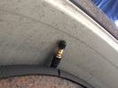
Tyre Valve Extension RLD plate24 views
|
|
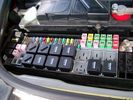
Picture of the engine compartment fuse panel5780 viewsEngine compartment fuse panel located near the battery. This is where F3E, (5 amp), F26E, (20 amp), Fuseable link 10E, (60 amp) and Relay 7E, the now upgraded 70 amp air compressor motor relay, part number YWB500220, (E is for Engine compartment fuse box), are all located. Fuse F35P, (5 amp), is inside the Passenger compartment behind the lower glove box door.
To keep the suspension from going down to the stops when driving, (or parked), it appears that it is only really necessary to remove F26E to depower the exhaust valve and generally keep all the valve block solenoid valves in a closed position trapping whatever air is within the air springs. F3E gets its power thru F26E, so when F26E is removed, the F3E circuit is automatically de-powered. F35P is more interesting in that battery power goes thru the ignition switch and F35P and then into the air suspension control unit. Apparently however, if F26E is removed, removing the F35P is not needed even when the engine is running.
With all fuses still in, if you have a problem, in practice, ideally, the compressor still works and will raise the 3 to an appropriate height. If so, one can then shut the engine off and allow the computers to go to sleep and then you remove the fuse(s). In actual practice, it seems that one need only pull the F26E fuse and can do so with the engine running. All the same, one might consider that the 3 is first a mobile computer, and secondly a 4x4. Computers prefer to go to sleep before the plug is pulled on them, however given that F26E circuit is always alive, then the computer never sleeps. With the fuse(s) pulled, and if you are still up, you can now be a 4x4 instead of a low rider. The whole purpose of the fuse pulling exercise is to depower the one and only system exhaust valve that is physically located within the compressor unit, (to keep it from opening), and secondarily to keep closed the four air spring solenoids within the block valves. This also shuts the air compressor down and stops the air compressor from making air even if the compressor is still good. That is why you initially need the fuse(s) in to allow the compressor to make air if it can.
|
|
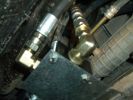
Valve System487 views
|
|
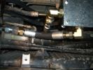
Valve System Connections466 views
|
|
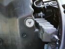
Bottom of airbox, showing one-way valve and locating lug176 views
|
|
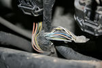
Cross-link valve broken wire115 views
|
|
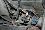
connectors suspension valve133 views
|
|
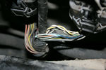
Cross-link valve broken wire109 views
|
|
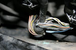
Cross-link valve broken wire97 views
|
|
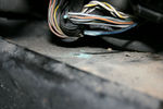
Cross-link valve broken wire98 views
|
|
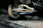
Cross-link valve broken wire105 viewsLeft front inner wheel arch
|
|

cycle tyre valve onto the jerrycan47 views
|
|

Fuel Schrader Valve26 views
|
|
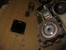
Exhaust valve231 views
|
|
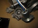
Pilot exhaust valve228 views
|
|

Pilot exhaust valve solenoid214 views
|
|

Exhaust valve plunger195 views
|
|

Exhaust valve 255 views
|
|
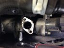
EGR replacement29 viewsUndoing the right hand valve is much easier that the left one.....
|
|
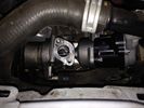
EGR replacement19 viewsNew valve in place. Looking nice and shiny!
|
|
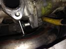
EGR replacement21 viewsThe left EGR valve is tight up against the turbo boost pipe. This make insertion of the long bolts difficult!
|
|
BAS Reemap UK EGR Valve blanking kit 18 views
|
|

This is what your engine eats when the egr valves are functional20 views
|
|
Butterfly valve15 views
|
|
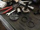
what you should be left with after the blanking procedure8 viewsApart from this, you'll also have to remove the pipes that connect the valves to the airbox. Not mandatory, but a proper job well done
|
|
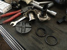
Butterfly valve and varous leftovers from the EGR valve blanking and pipe removing17 views
|
|

airbox with EGR blanking kit installed 16 views
|
|
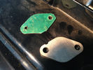
BAS Remap UK blanks for the EGR's 18 viewsnotice i also added a garage made seal, just to make sure there are no problems
|
|
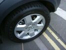
Goodyear Wranglers with the TPMS valves883 views
|
|

Thread upload11 viewsImage uploaded in thread 109340
|
|

Thermostat Housing LR005631538 viewsWhen the time comes to install a new thermostat, consider installing the whole housing instead.
Advantages are the thermostat is correctly installed, (not as simple as it should be); you get all new plastic and that is important, plus a new coolant temperature sensor and also a new heater coolant bypass valve, the secret part no one realizes is also within.
The cost of the whole assembly is not much more than the cost of a factory thermostat and the effort to replace all is not as difficult as it might seem.
|
|

Leaking Reservoir Valve24 views
|
|

67 views
|
|

65 views
|
|

70 views
|
|
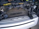
19mm wiring loom in trough behind bumper and in front of rad792 viewsThe 19mm wiring loom is large enough that a maximum of six 6mm air lines can be fished thru as required. The loom runs from the FASKIT panel located in the engine compartment behind the left front headlight, down and across in front of the rad and then down to the front axle valve block located behind and below the right fog light.
|
|
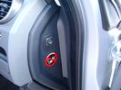
Air Suspension ECU Fuse 35P cut off switch.3821 viewsThis shows the SPST rocker switch mounted in the blank plate installed in lieu of a manual passenger side air bag shut down switch - now automatic via passenger seat pressure switch. Fuse 35P (5 amps) is located in the interior fuse box behind the lower glove box and protects the ignition power supply to the Air Suspension ECU. When the SPST switch is moved to the OFF position, the RAISE /LOWER switch on the centre console is not powered, and hence does not function. As such, some signals from the wheel height sensors and CPU are ignored. By itself however, removing F35P will probably not stop the 3 from self dropping, particularly after the engine is turned off.
Fuse F3E, (5 amps), located in the engine bay fuse box by the starting battery protects the circuit that provides feedback to the Air System ECU indicating that the Compressor Relay has successfully operated and that the Air Compressor is or should be operational, can also be removed, (but is probably not totally necessary), as it gets its power thru F26E. Hence Fuse F26E, (20 amp), also located in the engine compartment fuse box is the fuse that must be removed. This fuse protects the circuit that provides full time battery power to the Air System ECU. When in place, current thru the fuse powers the periodic re-levelling action, (usually lowering a bit with that brief air release noise), that often occurs when the vehicle is parked and the engine is off.
Removing F26E fuse will stop the auto levelling action and also inhibit any other down to the stops signals, (engine running or not). When F26E is removed, no power can flow thru to F3E, hence removing F3E is more for insurance than an absolute requirement. The same with F35P, removing F26E removes primary full time power from the Air Suspension ECU, and hence removing the F35P fuse should not really be required either as long as F26E has been removed.
|
|
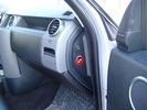
Air Suspension ECU Fuse 35P Shut Off Switch2635 viewsA more distant view of the shut off rocker switch in the ON position which is the normal position for when all is working as Land Rover intended.
Ideally, (but not totally necessary), the F35P circuit should be powered or de-energized after the various computers have gone to "sleep".
Similarly, removal of the F26E or F3E fuses is preferable after the computers have all gone to sleep but it appears that no real damage will be done if the fuses are removed while the system is energized. Pulling F26E is the main full time fuse that powers the air suspension computer. As such, once F26E is removed, pulling F3E is not really required.
Power for the compressor goes thru the 60 amp fusible link and relay, however control of the relay is via the air suspension computer so depowering the air suspension computer effectively depowers the air compressor and the internal exhaust valve relay/port.
|
|
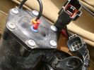
Compressor Electrical Plugs 1406 viewsThis shows the two electrical connectors; the two pronger is the power to the compressor, and the multi-pin connector carries control signals. Also the temporary red plug is where the 6 mm tubing from the centre valve block connects. This line carries both the compressor and exhaust air to and from the springs.
|
|
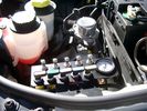
View of mounted panel from front left side878 viewsNote that all valve handles are shown in the OFF position, (the trouble position). In this case, the air that is in the air springs, (if any), is trapped in there - that is the valve blocks cannot vent whatever air is already in the air springs as the air lines between the springs and respective valve blocks are closed off by the FASKIT valves. In operation, there may be only trouble with one air spring, (perhaps a wheel height sensor), and as such, only one valve would need to be closed. If there was complete air compressor failure, then all valves would be closed and then as required, each spring could be manually filled from an outside clean dry oil free air source.
|
|
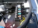
View of mounted panel from front left corner737 viewsI drilled a hole for the supplied 6 mm tie down toggle bolt in a flat portion of the wing on which the panel sits. I inserted a 50 mm flat rubber washer between the wing metal surface and the underside of the black painted panel plate; also a 40 mm flat rubber washer between the supplied fender washer and the metal plate - just seemed like a good idea so surfaces mate well even if wing metal not completely flat.
|
|
View from front left side looking towards rear aux battery compartment under cover 647 viewsAs there is no Fuel Burning Heater in the NAS V8 petrol vehicles, there is space available to install the FASKIT panel here. The piping is such that each air spring can be isolated from the air system and then filled one at a time manually via the Schrader valve. There are five Schrader valves and five shutoff valves. The fifth valve nearest the gauge controls air from the compressor, and can provide fill up air via a jumper fill line assuming the compressor is still operational.
|
|
Empty space in NAS LR3 for location of FASKIT panel599 viewsThe empty space is available as the North America Spec gasoline engine LR3's do not have the Fuel Burning Heater installed. The air lines from the four air springs and the air tank will appear to rise up from under the headlight assembly. The lines to the front block valve assembly located behind the front right fog light will sort of run within the bumper across the front of the radiator down into behind the righthand fog light. The rear lines somewhat follow the path of the existing air feed line from the front valve assembly to compressor. Rather than be located between the left front fender liner and left metal wing however, the four lines will feed thru the empty wing space inside and above the wheel well arch and exit down by the left front mud flap. From there, the lines run along the left frame member above the air tank and then parallel the frame over top the compressor to the top of the rear left air spring where the rear air block valve assembly is located.
|
|
19 mm wire, (tubing), loom rising from below at left headlight657 viewsFrom the FASKIT panel, five air lines fit in the 3/4" (19mm) wiring loom and feed to the front air valve block located behind and under the right front fog light.
|
|
Wiring, (tubing), loom exiting temporarily from the front right fog light.569 viewsThe front axle air valve block is located just behind and below the fog light. Access to the valve block is by removing the right front fender liner, (or the bumper). The FASKIT lines are attached to the left and right front air spring lines at this location; also compressor air is taken from this location as well. Cutting the lines at as few different locations makes it easier to find leaks at a later date. As above, five 6mm air lines run from the FASKIT panel to the front axle air valve assembly and run within the loom. Two pair of the lines are for control of the air springs, and the fifth line taps the air supply at the valve block assembly off the compressor. This will be the air source line rather than tapping in directly to the high pressure air tank.
|
|

LTB00121 - Technical Bulletin - Remove Install Automatic Trasmission Valve Body Assembly70 views
|
|

LTB00221 - Technical Bulletin - Tire Valve Stem Damage During Manual Tire Pressure Checking58 views
|
|

LTB00269 - Technical Bulletin - Air Suspension System - Compressor Delivery Valve and Drier Replacement Software Update2926 views
|
|

94 views
|
|

LTB00768v2_-_3_0L_TDV6_Valve_Cover_Split_and-or_Cracked31 viewsLTB00768v2_-_3_0L_TDV6_Valve_Cover_Split_and-or_Cracked
|
|
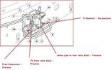
Thread upload3 viewsImage uploaded in thread 178308
|
|

21 views
|
|
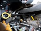
D3 MY2009 Dipstick8 viewsTwo brackets on the dipstick tube obstruct the LH EGR valve and its cooler. They must be separated in situ (Torx30 x 2) before lifting them out.
|
|
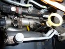
D3 MY2009 Dipstick11 viewsTwo brackets on the dipstick tube obstruct the LH EGR valve and its cooler. They must be separated in situ (Torx30 x 2) before lifting them out.
|
|
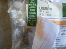
LR020590 KIT - COMPRESSOR 1481 viewsThere are 4 main parts you can get besides a whole compressor. This is the one with only a spring, o-ring and rubber valve.
YWB500220 electrical, fuse & relay, relay ENGINE COMPARTMENT, 70 amp 1
LR020590 KIT - COMPRESSOR 1
JPO500010 KIT - COMPRESSOR 1
VUB504700 - Dehydrator PARTS
|
|

MAP sensor 44k miles, EGR valves not blanked164 viewsUsed Miller's Sport 4 then whatever it has become, for last 22k
|
|
EGR Pipe Clips831 viewsRemove the 2 circled clips to disconnect upper ends of EGR pipes from the stub pipes fitted to the EGR butterfly valve housing.
|
|
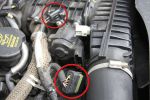
EGR Butterfly Valve Actuator and Air Box Connectors931 viewsRemove the 2 circled plugs.
|
|
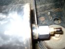
Reservoir Air In fitting installed 1661 viewsSchrader valve installed. Shop air can now be introduced into the tank to facilitate the raising of the 3 when there has just been a failure of the onboard air compressor rather than the electronics or valve block wiring etc.
Air could also be sourced from this point, however the purpose of the modification is air in, not air out as the air pressure normally runs above 200 psig, too high to be safe for routine use unless a pressure reducing regulator is added per the Mitchell Bros kit.
|
|
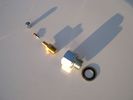
Reservoir Air In fittings exploded view 1893 viewsThis shows the fittings required for the mod. The reducer adaptor requires a 27mm socket and is M20 x 1.5 male thread x 1/4" NPT female. The 1/4" male NPT Schrader valve has the standard valve core removed and an AN/MIL spec aircraft oleo strut valve installed instead.
A standard automobile valve is rated at 200 psig, (14 bar); the air tank runs closer to 244 psig, (16.8 bar), with the relief valve set to open between 334 psig, (23 bar) and 370 psig (25.5 bar). The aircraft valve is rated at 2,000 psig, (138 bar).
|
|
Reservoir Bung 24mm socket 1155 viewsThis is the view of the air tank at the end nearest the front left wheel. This is what you see before you do the mod. The other view is after the mod.
On pre 2008 models, there is this 24mm socket hex head bung, M20 x 1.5 thread, that can be unscrewed and the Schrader valve assembly installed instead. On newer 3's the bung hole was deleted from the front end of the air tank; hence the mod as described, is then not possible.
|
|

Thread upload3 viewsImage uploaded in thread 193769
|
|
Thread upload14 viewsImage uploaded in thread 126053
|
|

Thread upload4 viewsImage uploaded in thread 194659
|
|

Thread upload2 viewsImage uploaded in thread 132287
|
|

Thread upload1 viewsImage uploaded in thread 196593
|
|

Thread upload1 viewsImage uploaded in thread 196593
|
|

EGR Stub Pipe866 viewsThis is one of the stub pipes that are fitted to the butterfly valve housing. When both are fitted, they meet in the middle of the housing and must present quite an obstruction to the flow of air to the engine inlet valves! Look how cruddy it is. All that muck is being fed to your engine. Ugh!
|
|
Suspension Valve Block & Wiring removed for Re-Routing141 views
|
|
Thread upload27 viewsImage uploaded in thread 162709
|
|
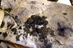
EGR Valve Muck53 viewsSome of the EGR gunge removed from the air duct
|
|
![Filename=Technical Service Bulletin SB034 SB036 Vehicle Enhancement Program[1].pdf
Filesize=959KB
Dimensions=0x0
Date added=17.Jun 2010 Technical Service Bulletin SB034 SB036 Vehicle Enhancement Program[1].pdf](images/thumb_pdf.jpg)
Technical Service Bulletin SB034 SB036 Vehicle Enhancement Program2390 viewsOn page 6 and following are the Land Rover service bulletin instructions as to how to install delivery valve and exhaust valve repair kit JPO500010; also a list of previous compressor model numbers as related to the 3. The new delivery valve is easy to install, the exhaust, not so easy. Note that this in not the more recent TSB that reduced the operating pressure of the compressor via a software fix and also recommended replacement of the air compressor 70 amp relay. See the F35 album near the bottom for the relay material.
|
|

Thread upload0 viewsImage uploaded in new thread
|
|

Thread upload13 viewsImage uploaded in thread 121273
|
|

Tyre pressure monitoring valve23 views
|
|

TPMS Valve16 views
|
|
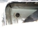
Trimmed Valve124 views
|
|

Thread upload2 viewsImage uploaded in thread 205894
|
|

Tyre Valve Dust Caps177 views
|
|

18 views
|
|

17 views
|
|
27 views
|
|
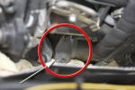
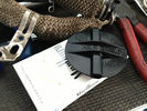
EGR Valve Blank1083 viewsHere is one of the blanks fitted to the EGR valve.
|
|

Valve Cover RH.pdf486 views
|
|

Thread upload1 viewsImage uploaded in new thread
|
|
Valve119 views
|
|
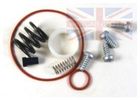
Thread upload12 viewsImage uploaded in thread 119960
|
|

Thread upload45 viewsImage uploaded in thread 126636
|
|

Thread upload36 viewsImage uploaded in thread 126636
|
|
Thread upload0 viewsImage uploaded in new thread
|
|
Thread upload1 viewsImage uploaded in new thread
|
|
Thread upload2 viewsImage uploaded in new thread
|
|
Thread upload0 viewsImage uploaded in new thread
|
|
Thread upload1 viewsImage uploaded in new thread
|
|

Thread upload2 viewsImage uploaded in new thread
|
|
Thread upload8 viewsImage uploaded in thread 164348
|
|

20 views
|
|

Thread upload3 viewsImage uploaded in new thread
|
|

Thread upload1 viewsImage uploaded in thread 190187
|
|
Thread upload13 viewsImage uploaded in thread 200357
|
|

Thread upload5 viewsImage uploaded in thread 175831
|
|

Thread upload10 viewsImage uploaded in new thread
|
|

0 views
|
|
Thread upload2 viewsImage uploaded in thread 156265
|
|
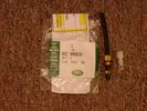
Voss System 203 connector 6 mm for valve blocks 905 viewsThis is Land Rover part number RQC000030, the Voss fitting for the axle valve blocks. I think it is a Voss System 203 6mm fitting, Voss part number 5 2 03 11 01 00.
The parts bag comes with the white plug inserted in the brass threaded bit with what is called the brass cutting ring placed on the tip of the white plastic plug. The idea is that one screws, (M10 x 1 thread), the brass insert into the appropriate hole with the white plug still in the brass insert. Once the brass is tight, (12 mm wrench), then the white plug is pulled from the assembly leaving the cutting ring down inside and under. One then pushes in the 6 mm tube end about 20 mm or so and the tube slides down thru the brass cutting ring, (2 internal sloped one way cutting ridges). When the tube is in far enough, one pulls upwards a bit and the ring cuts into the plastic such that the tube will not pull out. To remove tube, one unscrews the brass nut and all comes out, sort of like I have shown with the short piece of 6mm tubing. The white plug is a throwaway item upon install of the tubing.
|
|

Voss B203 Fitting Install957 viewsNote on the first page, the reference to DIN 73378 and D74324 and also PA11 and PA12 material when referencing suitable spec nylon (polyamide) air line for motor vehicles. I think some of the 6mm fittings used on the 3 for the valve blocks are the System 203 type and called up as Land Rover part number RQC 000030. The Voss part number is I believe 5 2 03 11 01 00.
|
|

Voss System 203 Connector cut thru, (similar to in valve block).678 viewsThis is a cut thru of a Voss System 203 connector. The top third of it is similar to the connector that holds the three 6mm plastic tubing lines into each of the front and rear valve blocks.
I say top third, as per the other pictures, the 3 has a Voss assembly that threads into the plastic of the valve block, whereas in the cut thru above, the Voss brass assembly is threading into the brass body of a metric threaded adapter for threading into a standard type metric threaded hole. Note also the two one way sloping ridges of the cutting ring, and the two interal O ring seals that mate with the plastic tubing. There is additionally the small squashed O ring to provide a seal related to the external thread of the Voss cutting ring assembly; (similar to the larger O ring for the brass body external thread).
|
|
Thread upload10 viewsImage uploaded in thread 207641
|
|
Thread upload20 viewsImage uploaded in thread 135237
|
|
|
|
|
|