| Search results - "wire" |
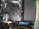
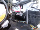
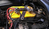
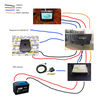
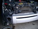
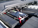
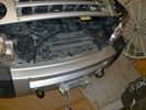
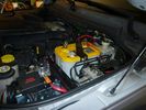
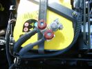
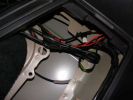
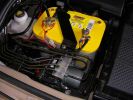
139 viewsThe weatherproof junction box fits neatly down the front of the battery, all contained inside the battery box.
|
|
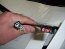
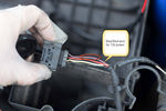
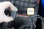
heated seat (base) wiring411 viewsThe Small connector takes the plug from the seat back pad, the larger connector (with red) is fitted into the multiplug casing uder the seat - the male side of this is already pre-wired.
|
|
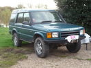
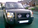
51 viewsD44 front winch bumper. Ali washer bottle. D44 rear h/d bumper. centre diff lock. 235x85x16 pirelli muds. OME +2" springs & shocks. front diff guard. side tree bars. wired for roof CB. Aux fuse block. safari snorkel. extended wading tubes. the list goes on...
|
|

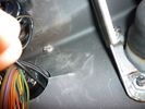
Put a link wire in these 2 holes (use a fairly thick wire ) - compressor will start ..you do not need the ignition on 941 views
|
|

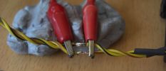
Morsetto - Clamp35 viewsPer la riparazione ho utilizzato un morsetto per fili elettrici.
To repair I used a clamp for electrical wires.
|
|
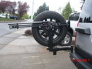
highlift and new sensor wire loom30 viewsNew wire loom added to protect sensor wires and keep things sanitary looking
. Highlift jack mount arms added and gas strut
|
|
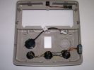
207 viewsRoof panel with wired switches and PTI microphone
|
|

Reversing monitor view, wireless receiver behind gear lever93 views
|
|
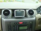
TomTom GO910 with no trailing wires380 views
|
|
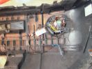
Pre-wired loom is an easy fit1047 views
|
|
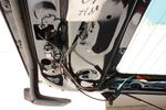
29 viewsRouting the camera wire
|
|
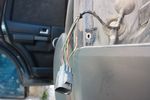
94 viewsReverse wire stripped. I then soldered the wires which I need to this wire and close up with self amalgamating tape. This way I don't damage any original wires (except for the insulation) and it's easily reversible by desoldering
|
|

83 viewsReverse wire tapped into
|
|

97 viewsOut at the C pillar. From here wires were threaded through the rear seatbelt anchor point into the commercial box, which is the hub of all the wiring and CarPC installation
|
|
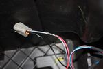
109 viewsThis is the plug for the accessory socket at the rear of the cubby box. On commercial D3 such as this one, there is no accessory socket so this plug is unused. I tapped into the 12V wire as an ignition feed. This will feed a relay coil which opens up power from the aux battery. Like this I can still retro fit and make use of the accessory socket later on.
|
|

68 viewsJungle of wires coming out of the cubby box
|
|
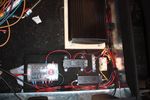
75 viewsAll wired up!
|
|

BOOT Rear Audio controls14 viewsBOOT rear audio wires
|
|

BOOT Rear Audio controls16 viewsBOOT audio wires
|
|
Reverse Camera wires7 views
|
|
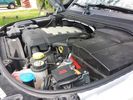
Winch Power upgrade319 viewsUsing 2 warn kits, and removing one of the wires to use on another project. The purpose was to replace the power and ground wire. I used Warn kits, which are 4/0 Welding cable. The original red #4 warped from getting a little too worn. The 2nd
Battery #1 Deka 9A94 AGM Intimidator, Battery #2 Deka 9A47 AGM Intimidator WARN 36080 28" Quick Connect Cable X 2, WARN 26405 Quick Connect Cable 7' X 2, WARN 15901 Black Cable X 1 -- winch control 72" X 1 https://www.facebook.com/DifferentialPartsUS
|
|

9 viewsWire
|
|
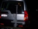
As it was when I had hd enough at night, next day to wire in HF antennae293 views
|
|
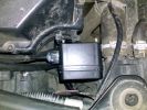
Possible Location for wireless remote box situated to the front of the airfilter housing113 views
|
|
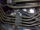
Allbright Solenoid in Place & Wired to Winch101 views
|
|
Allbright Solenoid in Place & Wired to Winch102 views
|
|
25 Dash Loom45 views
|
|
position of buttons for Parrot phone102 viewsthis can be put basically anywhere as it connect via bluetooth to the rest of the system. It is self powered (lithiam battery in it) so just stick it anywhere with no requirements for finding a live wire etc
|
|
4 Dash Loom40 views
|
|
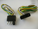
4 pin NAS flat connector from NAS small trailer382 viewsThe connector with the three exposed pins is the end that would commonly be located at the trailer hitch end, (front), of a small NAS lightweight trailer that has no electric brakes. This plug would connect into the flat 4 pin connector at the rear of the 3.
Note the order of the pin functions and wire colours: White is ground; the next pin is for tail/marker lights using the Brown wire; the Yellow conductor is for the left turn signal, and the far pin uses the Green conductor for the right turn signal.
There is no separate brake light conductor as NAS spec vehicles most often combine the brake and signal light functions to the same bulb filament rather separate filaments in different bulbs. The LR factory harness resolves that design difference.
Fortunately, the Land Rover NAS assembly pin order for the 4 pin flat plug maintains the above described conventions.
|
|
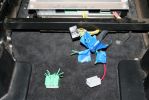
04278 viewsThe green wiring harness is the speaker outputs. Green is + and Green with white stripe is -. We tested all the wires with a 9V battery to figure out which went to what speakers then clearly labeled them as we did.
|
|
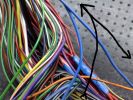
5 Dash Loom38 views
|
|
Thread upload2 viewsImage uploaded in thread 198354
|
|
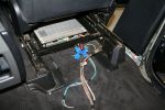
05270 viewsGetting all the wires ready to hack.
|
|
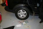
06257 viewsWires from the wiring harness of the V1000 to hook up.
|
|
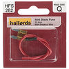
Mini Blade Fuse with Breakout Wire11 views
|
|
Thread upload26 viewsImage uploaded in new thread
|
|
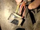
Broken wire Transfer box actuator motor harness 2 - temp sensor wire25 viewsBroken wire Transfer box actuator motor harness 2 - temp sensor wire
|
|
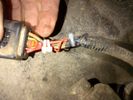
Repaired Transfer box actuator motor harness 2 - temp sensor wire24 viewsRepaired Transfer box actuator motor harness 2 - temp sensor wire
|
|
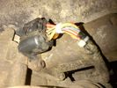
Repaired Transfer box actuator motor harness 3 - temp sensor wire26 viewsRepaired Transfer box actuator motor harness 3 - temp sensor wire
|
|

Alternator female plug looking down into top373 viewsThis shows the plug connected to the alternator wiring harness looking down into the top of the plug.
The cavity marked 1 is the AS or BATT SENSE and the wire colour most likely has Brown/Green on it.
The cavity marked 2 is the RC or ALT CON and the wire colour most likely has Red/White on it.
The cavity marked 3 is the L1 or ALT MON and the wire colour likely has Green/White on it.
I say "most likely" as the wire colours are not always the same on all vehicles.
Also the terminal 1 conductor destination is more likely C0570-175 rather than per the jpg.
The #3 pin is located closest to the big B+ terminal.
|
|
148 views
|
|

Amplifier wiring98 viewsChanges for converting High Line to Premium.
|
|

Thread upload23 viewsImage uploaded in new thread
|
|
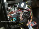
154 viewsInstall Hands free HCB-700 in A class
|
|
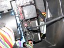
aux sockets relay - remove the relay and put in link wire 192 views
|
|

AUX wires?25 viewsIs this the AUX wires to tap into?
|
|
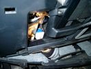
Brake Switch Visible thru Opening4975 viewsThe blue and white bit is the switch; the sort of gold appearing box,(it is really black), you will not see in your 3 as it is a Smooth Talker brand amplifier for my Blackberry phone antenna. This install is detailed in the SmoothTalker phone antenna section of my gallery.
One way to remove and install the switch is to lower the "horizontal" panel above the brake pedal as shown where the flashlight head is located. To actually remove the switch, you slide your hand thru the gap and rotate the switch clockwise 1/4 turn while watching thru the rectangular opening. Installation of the new switch is the reverse of above - 1/4 turn counterclockwise.
Before you remove the switch, note its orientation - horizontal with electrical wires to the left. That is the way it should look after replacement as well.
The second time I replaced the switch, I did it all thru the rectangular opening and did not remove the horizontal panel - that is experience helping out.
The knee kick you have to remove regardless. It is sort of hinged at the bottom so you just pull at the top and sort of rotate the knee panel and then pull upwards for two plastic "fingers" to clear the slots they reside in.
|
|

26 views
|
|
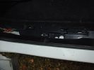
Rear passenger (left) wire harness channel42 views
|
|
Can Pair Repair84 viewsThis is the high speed CAN bus Pair. By over twisting and keeping the repair short i will maintain the very important twist. Good soldering is a must it looks ropey in this shot but it is not, note the heat shrink pre placed on the wires to the right.
|
|
9 views
|
|
Thread upload13 viewsImage uploaded in thread 111486
|
|

27 views
|
|

22 views
|
|

21 views
|
|
IPod wires15 views
|
|
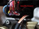
385 views
|
|

Thread upload2 viewsImage uploaded in thread 179494
|
|
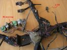
example problems113 viewsInspection showed another Cut Airbag connector, a Missing connector and a few rogue wires at the bottom, the silver one marked Lin, is for the LIN BUS and is supposed to be like that though
|
|
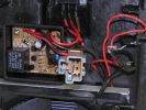
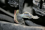
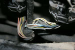
Wire photo210 viewscut wire close up
|
|

wire photo 2234 viewswires at a distance
|
|
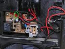
156 views
|
|
57 views
|
|
CounterAct Power Supply mounted 247 viewsPicture is blurred, however power supply is 3M two sided tape to the flat black plastic of the second battery compartment just under the antilock brake pipes to the fender side of the brake fluid reservoir. The white wire to the left rear coupler pad runs thru the firewall hole near the steering column. The blue wire to the right front coupler runs across and above the engine following the other wiring looms that cross the vehicle.
|
|
d3 canbus wire fault455 views
|
|
205 views
|
|
178 views
|
|
147 views
|
|
114 views
|
|
116 views
|
|
106 views
|
|
106 views
|
|
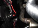
D4 hid fbh wire clearance185 views
|
|

A-Pillar 117 viewsWires run from the roof console along the A-pillar
|
|
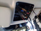
Wires installed for roof console123 views
|
|

Thread upload0 viewsImage uploaded in thread 178057
|
|
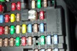
Tapa-Circuit Fuse Tap411 viewsTapa-circuit fuse tap fitted in existing fuseway provides extra fuseway which I have used to hard wire my Tomtom Sat Nav PDA. The fused output feeds into a female socket (Cigar lighter sized) into which the tomtom power adaptor is plugged. All hidden away behind the glove box.
|
|
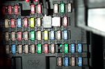
Tapa-circuit Fuse Tap435 viewsTapa-circuit fuse tap fitted in existing fuseway provides extra fuseway which I have used to hard wire my Tomtom Sat Nav PDA. The fused output feeds into a female socket (Cigar lighter sized) into which the tomtom power adaptor is plugged. All hidden away behind the glove box.
|
|
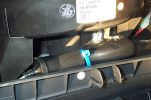
Hard wired tomtom498 viewsThe fused output from a tapa-circuit feeds into a female socket (Cigar lighter sized) into which the tomtom power adaptor is plugged. All hidden away behind the glove box.
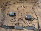
|
|
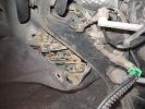
Brake sensor connector ( with 2 red wires connected)302 views
|
|
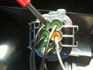
190 viewssignal wire pin 3 on rear of D4 rear light plug fit 6 ohm 50 watt resistor across here and common ground Pin 5 yellow terminal shown in next pic
|
|
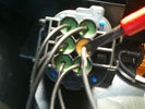
170 viewscommon groung wire pin 5 yellow on rear of d4 light plug
|
|

gvif scheme80 viewsSchema for gvif installation using reversing camera, wireless caravan camera, hitch camera and camera select when driving forward direction
|
|
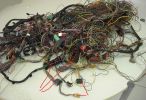
Donar Loom100 viewsThis ball of wires is from a LHD which has been opened and had all audio wires removed, however it is a gold mine for the bits i need. I have pointed out the connectors i know i need for starters near the bottom.
|
|
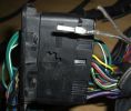
New Speaker Cables.111 viewsThis is the door connector, Main loom to Right, Door side to the left. to the top of the connectors you can see green and Green white wires which are the speaker ones. The door wiring is premium and has two pairs, the main loom was a 1 pair high line, so i am adding the pair you see (one already pinned up) to upgrade the loom to premium.
|
|
Picture of wire direct into headlight wiring181 views
|
|
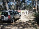
Locked gate and wire rope fence at start of Limeburners.68 views$11,000 fine if you are caught in a vehicle on the other side!
|
|
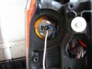
indicator lampholder, white wire connected to unused filament328 views
|
|
wire from reversing light131 views
|
|

Wires cut to lenght47 views
|
|

Timer wires tinned - yellow was re-done!48 views
|
|
Remote wires tinned - I did notice the red also needed re-doing!!!!47 views
|
|
Quick rigging using multimeter wires to check power to the timer...57 views
|
|
Used the wire connector that came with the timer - no probs!69 views
|
|
RR had a starter wire break359 views
|
|
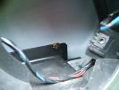
Overview423 viewsSharp edge of frame is dead centre of image.
Eroded "switched live" feed is blue wire high on the right
|
|
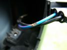
Close-up on wire408 views
|
|
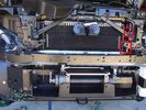
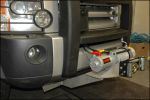
Installed winch with electrical solenoid connections163 viewsI routed the electrical supply (2 small wires) up the side of the radiator. You can see the unconnected wires inside the red boxes. I ended up connecting them on the radiator diagonal strut with cable ties. They are out of the way for any deep water transits there.
|
|
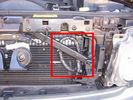
Installed winch electrical wires149 viewsWires which only power the solenoid are inside spiral wrap. They are also connected inside the wrap at the high point of the loop. Cable tied into place to prevent vibration rubbing.
|
|
its even got wireless remote controll as well as traditional wired controller192 views
|
|
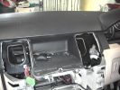
wires pocking through hooked up to base harness646 views
|
|
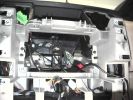
wires for aux input, 12 volt andmicrophone through the cubby floor662 views
|
|
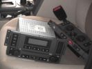
All the bits - don\'t let your wife see them like this!587 viewsHere\'s the stack all dumped on the passenger seat while i run the wires.
|
|

20 views
|
|
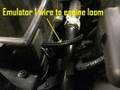
45 views
|
|
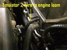
47 views
|
|

Thread upload24 viewsImage uploaded in new thread
|
|

Thread upload13 viewsImage uploaded in new thread
|
|

Thread upload16 viewsImage uploaded in new thread
|
|
49 views
|
|
208 views
|
|
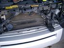
Wires under the bonnet 143 viewsLooking inside the grille - centre. No socket here.
|
|
Wires under the bonnet 141 viewsLooking inside the grille - centre. No socket here.
|
|

Fan Connector - wires pulled out39 views
|
|
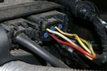
FBH connector on my 3 year old "S"150 viewsNote existing wire on 2nd row, pin 2.
|
|
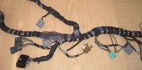
Finished Passenger Kick panel area131 viewsMissing connetor (left most grey) & wiring in, (plastic bracket was broke will use the one in the car) Airbag wires & connector to connector previously cut replaced (on top of grey one to right).
And you can even see the 2 new speaker wires going into the Pass door connector at the very bottom.
|
|
Extra wies at Amp area102 viewsAdditional speaker wires loomed in at Amp connectors can be seen being routed at the top.
|
|

Wiring Diagram Fog Lamps76 viewsR130 is the (R5 relay under the hood) The wire is blue grey that is hot when the high beams are on and opens the relay contact that turns off power to the fog lamps. North America Only
|
|
Thread upload13 viewsImage uploaded in thread 153063
|
|
Thread upload242 viewsImage uploaded in thread 3856
|
|

90 viewsRed FBH WBUS wire behind fusebox CJB
C2411 C2412
|
|

H9 lamp socket9 viewsWired directly thru HL Connector
|
|

High Beams Main Beams Wiring Diagram76 viewsThis is the wire colors and connections for Dipped, Main, and Side Marker lights
|
|

Thread upload12 viewsImage uploaded in thread 127724
|
|
Hvac_0157 views
|
|
The auxiliary battery21 viewsThe auxiliary battery in the bay.
As the wiring diagram I made shows, there's a wire leading to the fuse box in the rear. (is going through the key-switch)
The second one is going to the fog lights. The smaller cables which should be connected to the head-lights, are connected to the battery.
The third one is going to the compressor (via a switch) (sits before the key-switch)
A fourth one is going to the CB and battery check display (sits before the key-switch)
|
|
Harness chafing19 viewsWire insulation worn through with short to battery
|
|

Wires13 views
|
|

Tailage cable fix22 viewsThe broken cable elbow is fixed to the motor with two pieces of steel wire. I've also tied a string so I can open if the motor dies.
|
|
Rear wires 15 views
|
|

Suspension wire crimped33 views
|
|
Rear wires 17 views
|
|

LP scoped 222 viewsBy connecting a Low Amps probe to the fuel pump's voltage supply wire, you can view the pump's current waveform on a digital storage oscilloscope (DSO). The scope pattern will reveal internal wear in the brushes and commutator that may not show up in a traditional pressure or volume test.
Observing the waveform will show if the pump's amp draw is normal for the application or is high or low, and if the pump is operating at normal speed or is running slow. Problems such as a bad spot on a commutator or a short or open in the armature also will be obvious in the waveform.
A "good" electric fuel pump waveform will generally seesaw back and forth with relative consistency and minimal variation between the highs and lows. A "bad" waveform will show large or irregular drops in the pattern, with large differences between the highs and lows.
|
|
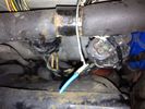
Broken wire RHS front wheel arch 28 views
|
|

Glowplug 2-wire test24 views
|
|

Glowplug 4-wire test19 views
|
|
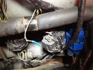
Broken wire front wheel arch 222 views
|
|

Series 3 300tdi14 viewsMy Series 3 patiently waiting for the D3 to stop breaking so I can rewire the thing properly!
|
|
69 views
|
|
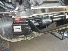
1868 viewsWinch control pack mounted, ready to wire now.
|
|

Switch is blue colour thing thru the rectangular opening.3177 viewsThe blue coloured plastic bit thru the rectangular opening is the brake light switch. The fist time, I found it easier remove the switch by dropping the horizontal plastic panel, (two screws), and then slipping my hand in and rotating the switch clockwise 1/4 turn. The second time, I was able to remove the switch thru the rectangular opening and did not need to remove the horizontal lower panel. Obviously, I had to remove the sloping knee pad panel, (note sort of hinged at the bottom so pull back from the top.)
Regardless, do not touch the brake pedal - just let it sit where it wants to. One has to first remove the angled knee pad panel that sits under the steering wheel. It can be pulled from the top corner at the door side. Pulling releases a pair of those U shaped metal clips that LR loves so dearly. You have to pull quite hard. The bottom is held by a couple of plastic fingers in a couple of slots so you pull at the top till the two clips release and then rotate the panel and pull upwards a bit.
To remove the switch, you rotate it clockwise and pull outwards. Rotating the switch clockwise automatically retracts the plunger back into the switch body away from the brake pedal arm.
Similarly when you install the new switch, the required 1/4 turn anti clockwise rotation action releases the plunger so it lays up against the brake pedal arm and at the same time, secures the switch in place.
To remove the electrical wires, the switch will drop below the horizontal pad and hang from the wires so unclipping the electrical connector plug is fairly easy to do.
|
|
113 viewswire extensions after soldering with heat shrink tubes.
|
|

105 viewswire extensions after soldering with heat shrink tubes.
|
|
110 viewswire extensions after soldering with heat shrink tubes.
|
|
110 viewsview of wires inside dash (from where plug was removed). I ran them through the pre-existing slit in the top of the glove box to wiring loom connector.
|
|
98 viewsPlug removed from left hand side of dash to locate wires from clove box
|
|

105 viewsextended wire running from glove box to loom connector.
|
|

bluebell an paddy41 viewsthe dogs
airdale x german wire pointer and a patterjack
|
|
GSM box end of the cable harness75 viewsGreen, blue & orange wires not connected
|
|

Wiring fault189 viewsThe wire and connector that corrodes causing a fault to the key fob locking
|
|

Junction box for all wires51 views
|
|
Day Light Driving lights272 viewsFitted and wired in. Looks good.
|
|
Cross-link valve broken wire115 views
|
|
Cross-link valve broken wire109 views
|
|
Cross-link valve broken wire97 views
|
|
Cross-link valve broken wire98 views
|
|
Cross-link valve broken wire105 viewsLeft front inner wheel arch
|
|
Reversing Camera wires12 views
|
|

D3 Rear Tailgate switch headliner connector8 viewsThe black connector in the headliner of a D3, showing the brown wire being pushed back and not making contact, and stopping the rear button from working
|
|
Can bus wiring repair19 viewsprevious owners repair to a can bus wire near the transfer case module
|
|
Battery Compartment Wire20 views
|
|
LED light - wired into power board115 views
|
|
EGR replacement16 viewsBack of left EGR cooler was a swine to replace the clip. Bound it with wire before using pincers to clip together.
|
|
EGR replacement17 viewsOld value with soot cleaned off with wire brush!
|
|
Thread upload13 viewsImage uploaded in new thread
|
|
Subwoofer Install275 viewsThe stock sub has 2 sets of wires running to it. Both of these wires lead back to the stock amp.
The new sub only needs two wires - a positive and a ground. So, we just cut the stock wiring harness off the wires in the tail gate and wired them together. On the other end of these wires, we did the same thing.
|
|
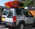
Kayaks with wire loop security.270 views
|
|

LA501-018 - Technical Bulleting - Safety Belt Pretensioner Wire Routing81 views
|
|
Thread upload0 viewsImage uploaded in new thread
|
|

Left Overs101 viewsMy donar loom is a bit smaller, and of course there is now a small pile of removed wires.
|
|
Got the lights on now (not wired up yet)397 views
|
|
Wiring harness for Hella 4000 Compacts260 viewsWired directly to the battery, all tucked away neatly now but can\'t find the picie
|
|

LR Electric Trailer Brake C2590 Female Connector606 viewsThis female connector, C2590, located up above and near the brake pedal is for the Trailer Electric Brake Controller hookup.
The Black wire in the bottom right is pin #3, the ground. The Blue wire to the left is pin #6, the Trailer Brake Controller output going to the rear trailer socket.
The White #4 wire is the 30 amp fusible link, (Link 6E in the engine compartment junction box), for the Brake Controller 12VDC power feed from the battery. Note that this would make a pretty good power source for CB radios and the like if no electric trailer brakes were required.
Pin #5 is a Green wire from the stop lamp switch, (the control input for the Brake Controller).
This plug is standard on all NAS (LR3) vehicles, but unlikely to be found on the D3 spec units.
|
|
19mm wiring loom in trough behind bumper and in front of rad793 viewsThe 19mm wiring loom is large enough that a maximum of six 6mm air lines can be fished thru as required. The loom runs from the FASKIT panel located in the engine compartment behind the left front headlight, down and across in front of the rad and then down to the front axle valve block located behind and below the right fog light.
|
|
Boot lighting panel, wiring side up 282 viewsThis shows the back side of the plastic cover panel on which the two LED lights are mounted.
Also of note is the SPST rocker switch to switch the new lights off independent of the the Land Rover W5W light.
The new light pair will only power up if the Land Rover light is powered and hence dims and automatically goes off along with the Land Rover light.
The Black wire is ground, the Purple wire is +12VDC.
|
|
Dust Seal duct taped back together 2281 viewsThis shows the dust seal duct taped back together; also the surplus wire rope exiting from the actuator area prior to being cut to length.
I do not think the sticky plastic membrane is a dust seal, but more of a cable protector to cover up the wiring bundle that is effectively sticking to the underside of the flexible membrane.
|
|
Flexible wire rope fishing leader 0.032" diameter exiting carpet 1949 viewsThis is all you see of the completed mod.
The short little angled "line" about an inch long that looks like a piece of debris and is located a few inches "above" the support cable is actually the wire rope release cable exiting from under the carpeted lift gate cover.
I drilled a very small hole in the carpet and pushed the 0.032" diameter release wire thru and then slipped the loose end under the black plastic.
To release with the lift gate etc closed, from the inside, just pull the loose end free from under the black plastic and gently pull wire about 5mm, (1/4"), and the upper door catch should release. You will have to manually push the upper door out wards to actually effect opening, but you will already be inside the rear cargo area so that part is easy to do.
The assumption is that the lower door latch still works electrically and hence, the lower lift gate half will open as normal by pressing the usual button on the top left of the lower door half.
|
|
0.032" OD metal fishing leader and lead fishing weight clamped to existing wire rope 2121 viewsI used a size #0 lead fishing weight as a clamp to attach the 0.032" diameter flexible wire rope fishing leader to the release cable.
The pictured weight is the smaller #00 weight, however it did not work very well so reinstalled with the larger #0 size. I clamped to the cable as what breaks is the L retainer that is hidden in the actuator and holds the cable. When the L breaks, it lets go of the cable so you hear the clicking but there is no opening action.
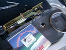
Clamping on to the cable is an attempt to resolve that reality; also if the actuator electrically fails, the release mod should still do the task. Note in the picture the two Torx T15 screws that hold the gold plate to the plastic case and also the two 8mm cap screws that have to be loosened to remove the actuator from inside the door.
|
|
Carpeted cover removed showing uncut dust seal and underside of carpeted cover. 1628 viewsNote that there are all sorts of electrical wires sticking to the underside of the dust shield - so be very careful when you cut thru the shield.
I used a box knife very slowly and was surprised at how many conductors there were running just under the shield membrane.
|
|
Dust seal cut; note electrical conductors right under dust seal 1627 viewsShows what is underneath when the dust seal is cut. Note the electrical conductors.
I used a box knife to cut the plastic and it was at first easy; then I seemed to hit something and fortunately I stopped - it was the wires - lots of them stuck right to underside of the sticky seal material.
Also shown are the two 8mm nuts in slots that you only have to loosen to release the gold actuator assembly.
|
|

NAS 7 Blade Round plus NAS 4 Pin Flat Vehicle end Socket528 viewsThis shows the function of each blade when looking into the connector at the vehicle end for the 7 pin NAS plug. The layout is the pin order for most new North American pickup trucks and the LR3/4.
The colour and gauge of the wires feeding into the back of the plug varies even within manufacturer model lines.
Also detailed is the flat 4 pin layout common on smaller trailers not having electric brakes. This includes most U-Haul rental trailers.
|
|
19 mm wire, (tubing), loom rising from below at left headlight657 viewsFrom the FASKIT panel, five air lines fit in the 3/4" (19mm) wiring loom and feed to the front air valve block located behind and under the right front fog light.
|
|
Wiring (tubing) loom at left headlight showing FASKIT panel 584 viewsThis shows the wiring (tubing) loom and FASKIT panel mounted to left wing. The loom moves a a couple of inches (50mm) towards the bottle once the headlight is put back in as there is not enough free space for the loom as located. The FASKIT panel is just visible at the top left corner of the picture.
|
|
Wiring, (tubing), loom exiting temporarily from the front right fog light.569 viewsThe front axle air valve block is located just behind and below the fog light. Access to the valve block is by removing the right front fender liner, (or the bumper). The FASKIT lines are attached to the left and right front air spring lines at this location; also compressor air is taken from this location as well. Cutting the lines at as few different locations makes it easier to find leaks at a later date. As above, five 6mm air lines run from the FASKIT panel to the front axle air valve assembly and run within the loom. Two pair of the lines are for control of the air springs, and the fifth line taps the air supply at the valve block assembly off the compressor. This will be the air source line rather than tapping in directly to the high pressure air tank.
|
|
Wire (tubing) loom on right to down into bumper 465 viewsThis shows the 19mm loom in the trough between the bumper and the rad as it drops down into the right fog light area.
|
|

Power and Heated Seats Electrical Schematic979 viewsThis 6 page pdf shows the wiring for the power adjustment of the front seats and seat heating for all the seats.
Re seat movement or the lack of, not only are there four related fuses, two 30 amp and two 5 amp, (one of each per seat), there are are two separate ground wires, perhaps of more significance than the power, if all movement on either side quits.
|
|

Stop Light Lamp Circuit pdf2492 viewsThis pdf shows the brake light circuit for the NAS LR3.
Note that power for the brake light bulbs can come either thru the brake light switch power feed /contacts plus also from the Hill Decent Control, (HDC), system relay located within the Central Junction Box, (CJB) - yes two separate sources of power for the brake light bulbs. This would tend to explain how a brake light circuit concern shows up as a hill decent fault message; also why lesser vehicles without hill decent braking mechanisms, (HDC), never display this sort problem when a brake light bulb or switch acts up. You never have a problem related to a system that does not exist.
Additional evidence of the relationship of the HDC and the tail light circuit is demonstrated by when the HDC actually acts to slow the 3 down, the brake lights automatically illuminate even if the slowing action was merely retarding the engine speed or shifting to a lower gear, (in other words, no foot on the brake pedal).
There is also a tie in to the Cruise Control and hence a failing brake light switch can affect cruise operation or just create false Cruise Control messages. To further complicate the issue, while there are no messages generated, operation of the radiator electro viscous fan can also be negatively affected by the fouled set of secondary contacts within the brake light switch. This is all because the NC contacts within the brake switch send misleading messages to the ECU.
While the ground wire design is similar to other vehicles, note the grounds for the brake light filament and the reverse light filament are common on each side. That means that if one has a non functioning brake light on one side, the reverse light may not also work or that some problem with the reverse lights could back feed into the brake lights. This situation while unusual, can result when grounds are corroded probably due to swimming in rivers and creeks or just routine driving in a marine environment.
|
|
12 views
|
|
Thread upload16 viewsImage uploaded in new thread
|
|
Main starting battery showing 1/2" hole drilled for power cable egress910 viewsView of OEM battery in Left Hand Drive LR3. This is supposed to be a Battery Group BCI 49 or H8 sized battery but in reality is the slightly shorter BCI 94R or H7 battery that fits easier lengthwise, (12 3/8" vs 14").
Note the 10mm hole drilled in plastic of surround to allow for entry of main power cable that runs between batteries. The cable bolts to a spare 6mm threaded hole in the OEM battery cable end; the light gauge wire runs to the front of vehicle to a connector for the CTEK MULTI US 3300 charger. Coloured felts, (red and green), are a material treated to reduce battery post corrosion. The OEM battery ground cable is only about a foot long and runs to an 8mm stud located on the inner fender just to the rear of the fuse case.
|
|

Thread upload1 viewsImage uploaded in new thread
|
|
Thread upload3 viewsImage uploaded in thread 126251
|
|
Thread upload1 viewsImage uploaded in thread 126251
|
|
Thread upload0 viewsImage uploaded in thread 126251
|
|
Thread upload17 viewsImage uploaded in new thread
|
|
All wires done92 viewsAll the cut wires have been replaced now, almost time for the loom tape.
|
|
new wires in85 viewsStarting to pull the new wires through.
|
|
Yaw Rate Sensor102 viewsThe connector for the Yaw Rate sensor was missing and some rogue wires near the Airbag connectors.
|
|
Firewall Plug539 viewsThis is the plug removed from the firewall, before cutting a hole to feed a wire through. Displace as much rubber as wire, so it is snug, but not to big, or you won't be able to snap it in.
|
|
Wire Run670 viewsThis is the inside the vehicle view of the hole, to run the feed wire through the firewall.
|
|
Firewall Plug614 viewsFeeding a guide wire through the new hole.
|
|
radar detector wires tucked up high426 viewsThe orange ties hold wiring sockets for floodlights (to be installed). Red tie holds excess wire for radar detector.
|
|

radar detector wires tucked up high414 viewsWires tied up neatly away from the electric motor, spool and gearbox.
|
|
wires tied up tight542 viewsThe Orange ties hold wiring sockets for floodlights (to be installed). Red tie holds excess wire for radar detector.
|
|
Traxide SC80-LR mounted714 viewsIn this position it fits properly without stress or stretching the plastic. A single small bolt holds it securely in place, and not toughing or rubbing on wires or suspension air lines.
|
|
Wire through fire wall63 views
|
|
Both connectors wired to aux battery90 views
|
|
118 views
|
|

69 viewsScreen originally, with wires out the bottom
|
|

69 viewsScreen now with wires out the rear end
|
|
permenant aux sockets ..place link wire here 158 views
|
|
278 viewsClose up of the cavity for the Nav screen. Here you can see the XM Satellite receiver antenna cable snaking across. It\'s the thin wire not bundled to anything. In the lower corner you can also see the power cable going to the glove box.
|
|

11 views
|
|
Pin swapping87 viewsExample of having routed the wires to their destination connectors to have the pins swapped out.
|
|

67 views
|
|

58 views
|
|
340 viewsConnection on the aux battey- Starter cable and supply wire
|
|
Radio Noise Suppression Capacitor NNW502820699 viewsThis is the radio noise suppression capacitor, part number LR020488 (previous NNW502820), that is mounted underneath and near the transmission. It is powered by fuse 10 amp F30E in the engine compartment. If F30E blows, (the fuse that also powers the transmission ECU), the problem is probably caused by the failed capacitor, not the ECU. A quick fix is just to disconnect the capacitor and replace the fuse as nothing bad seems to immediately result.
The above radio noise capacitor is not to be confused with LR004160, the ignition noise capacitor which is located under the black plastic engine cover on the right hand side above the air intake towards the rear of the engine.
The ignition capacitor is held on with a single 8mm bolt and a three wire electrical connector. Replacing the ignition capacitor as a routine maintenance prevention action at 100,000 miles, 160,000 km), has merit. It is a do it yourself kind of thing and easier to get at than the radio capacitor underneath.
|
|
Rear coupler pad located near rear left tail light 144 viewsThe rear coupler pad is not visible as it is located "below and behind", so to speak. Follow the loop of black plastic wire loom from right to left as the loop of loom covering the white conductor wire drops down "behind" to the flat metal surface the pad is glued to. The pad is attached to the flat metal surface via a 3M sticky on the backside of the coupler pad.
|
|
FBH red wire cut and crimped to new blue wire136 views
|
|

Thread upload21 viewsImage uploaded in thread 91
|
|

Rosen Owners Manual894 viewsThis 28 page Owners Manual is the Rosen version written specifically for the A10 model DVD Video Game Entertainment System player that may in attached to the roof of your 3.
Discussed is how to use the remote control, the wireless headphones, the TV feature if installed, and how to change from 16:9 widescreen format back to the older 4:3 format.
|
|
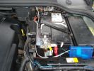
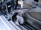
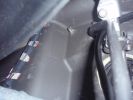
153 viewsI routed the white signal wire from the junction box which I positioned at the side of the battery, back and under the bonnet seal.
|
|
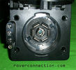
NAS 7 pin + NAS 4 pin Flat Trailer Socket308 viewsThis is the vehicle end of the NAS trailer harness that is located behind the removable plate centered within the rear bumper by the towing loop. Re the four pin flat connector, from the bottom, the exposed bare lower pin is the ground, usually the White wire on a NAS trailer. The next pin up is normally a Brown wire on a trailer and is for the Tail Lights. The third pin, normally a Yellow wire, is the left signal light; the top pin, normally a Green coloured wire, is the right signal light.
Re the round connector, from the notch in the plastic surround, clockwise, the first blade is ignition controlled +12VDC battery power, (only alive when engine running), and on the Land Rover factory harness is an Orange wire; on a NAS trailer, usually Red but perhaps a Black wire.
Next blade clockwise at 3:00 o'clock above, is the Right Turn signal light, a Green wire on the LR harness, and also on a NAS trailer.
At 5:00 o'clock, the next blade is for the Electric Brakes and is Blue on both the LR harness and on a NAS trailer.
The Ground wire is next, White on both the LR harness and on a trailer.
At 9:00 o'clock above, is the Left Turn signal, Yellow on both the LR harness and on a trailer.
The last blade to the left of the line up notch is the Tail Light circuit. On the LR harness, the wire colour is Brown with two White stripes and on a NAS trailer, Brown.
The centre pin is for the Reverse Back Up lights and is Black on the LR harness and often Purple on NAS trailer wiring but can be Black also.
Note that when the socket assembly is installed on the 3, the notch in the plastic surround is on the left - that is rotated 90 degrees anticlockwise to the picture above. In other words, When installed on the 3, the 4 pin flat connector lays horizontal and is located below the round socket.
|
|
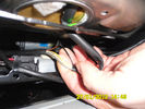
77 viewsThese are the wires to heat element
|
|
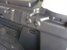
2 new rear 12v outlets933 viewsI added these two after market 12v oulets that are directly wired via a 30amp fuse to the aux battery. Why 2? Well you can never have enuff in my experieince... There\'s also a 12v socket wired to the ignition on the other side.
|
|
12v outlet wires859 viewsonside the drivers side rear hatch, whos the wires joined up for the rear sockets.
|
|
Installed and wired863 viewsShows the wiring loom to the isolator, the feeds (fused link) to the rear outlets and the other feeds are for the battery meter
|
|
Discarded cut wires80 viewsThese are Earth wires that have been completely replaced.
|
|

The little guy playing a wireless game57 views
|
|
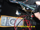
multiplugg under driver seat60 viewsThis picture is takin when diagnosing the heated seat element.
This show that there is 14volts to the elements on these wires.
|
|
Thread upload1 viewsImage uploaded in thread 177333
|
|
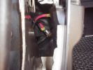
120 viewsThe signal wire then drops into the aux battery box and through the bulkhead grommet
|
|
Signal wire through aux battery box to grommett124 views
|
|
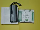
Upper Hatch Release Switch LR Part Number YUZ500020676 viewsThis is the Range Rover Sport switch, Land Rover part number YUZ500020, as it comes out of the box. Note the JAE, (Japanese Aviation Electronics), male wiring connector installed on the end of the power lead.
The rubber cover of the switch is sealed to the plastic body of the switch whereas in the previous switch design, there was no sealing. Also the replaced switch was hard wired into the same harness as the license plate lights - no JAE connector in other words.
|
|
Wire swapping91 viewsPulling out the old cut wires while routing in the new, you can see some already done in the lower loom body. The loom will be re wrapped at the end so i only need to hold it in place periodically at this point.
|
|

Thread upload2 viewsImage uploaded in thread 23845
|
|

Thread upload1 viewsImage uploaded in thread 23845
|
|

Thread upload5 viewsImage uploaded in thread 23845
|
|
Thread upload1 viewsImage uploaded in thread 23845
|
|

Thread upload1 viewsImage uploaded in thread 23845
|
|

Thread upload3 viewsImage uploaded in thread 23845
|
|
Thread upload2 viewsImage uploaded in thread 23845
|
|

Tekonsha Ford Brake Controller Adapter part number 3035-P275 viewsThis is the adapter cable between the Brake Controller and the existing C2590 female plug located near the brake pedal on NAS spec LR3's. The flat 4 pin plug of the adapter cable connects to the Controller; the rectangular 6 hole male plug to C2590.
There are only four conductors in the adapter cable, but one will see five pins within the Land Rover C2590 plug. The #2 pin is not required for the NAS setup. #2 pin is the circuit between the head lamp switch and vehicle side running lamps required in the civilized world.
The single pin at the bottom in the picture is #3 and on the Land Rover, a Black wire tied to ground. The other pin at the bottom and across to the left is #6, and Blue on the Land Rover. This is the Brake Controller output to the trailer socket at the rear.
#4 is the pin at the top left, and is a White coloured wire from the battery. Pin #5 is from the stop light switch, and is Green on the Land Rover.
Note that the adapter cable colours do not necessarily follow all the above referenced Land Rover colours.
|
|

Tekonsha P3 Electric Trailer Brake Controller model 90195291 viewsOne model of electric brake controller that is commonly used on the LR3 is the Tekonsha P3 unit, model number 90195. It mates up to the LR3 with a custom "Ford" adapter cable, Tekonsha part number 3035P. No wire cutting or splicing is necessary - just mount unit and plug adapter cable in.
|
|

Thread upload12 viewsImage uploaded in thread 123317
|
|

Thread upload16 viewsImage uploaded in new thread
|
|
Amdeal 30ft / 10M USB Digital Microscope Cable Wire Endoscope Camera Video Recording Inspection Pipe Camera - Waterproof, 4 LED Lights27 viewsUnder XP system, can watch video directly without install software. By using our software, can take photo,record video, and save the video in the PC. Such USB microscope widely used to inspect tube, check the body, magnify stamps, coins, antiques, insects, electric circuits, machines, fabrics, food, decorations, etc. Please notice that the wire camera is designed for industrial use, not for medical use.
Camera: 1/6" VGA COMS
Pixel: VGA 300K
Resolution: 640x480,352X288,320X240,176X144,160X120
Capture Resolu
|
|

Thread upload25 viewsImage uploaded in thread 103930
|
|

Wire Wicking23 views
|
|
207 viewsHands Free Kit install A Class
|
|

10 views
|
|
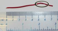
EPB Wire156 viewsThis wire came from somewhere in the EPB circuit and was the cause of my EPB not working. Circled in the picture is the broken part of the wire and just to the right of the break (also within the circle) you can just see a slightly thinner part where the wire has chaffed, removing the insulation.
|
|
Thread upload4 viewsImage uploaded in thread 130164
|
|

Thread upload7 viewsImage uploaded in new thread
|
|

Thread upload11 viewsImage uploaded in new thread
|
|

Thread upload4 viewsImage uploaded in new thread
|
|

Thread upload5 viewsImage uploaded in new thread
|
|

Thread upload5 viewsImage uploaded in new thread
|
|

Thread upload4 viewsImage uploaded in new thread
|
|

Thread upload5 viewsImage uploaded in new thread
|
|

Thread upload3 viewsImage uploaded in thread 191723
|
|
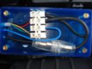
119 viewsConnector block, fuse etc all fits inside. Drilled the holes myself. Should really of used red wire for the +tive, but didnt have any.
|
|
wired landing131 views
|
|
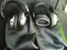
Wireless Headphones for RSE47 views
|
|
176 views
|
|

Thread upload3 viewsImage uploaded in thread 194623
|
|
WPC256 views
|
|
WPC154 views
|
|

New Wiring Overlaid99 viewsSport loom gives me length info to position replacement connector and its wiring in. Her you can see the new wires lying over the top of the cut of ones.
|
|

187 views
|
|

Parrot install180 views
|
|

32 views
|
|
Thread upload27 viewsImage uploaded in thread 138935
|
|

Wiring loom for the parrot186 views
|
|
whats this58 views
|
|

parrot install190 views
|
|

282 views
|
|

Overlaid wires95 viewsOverlaid wires draped to floor ready to be inserted into loom.
|
|

Thread upload1 viewsImage uploaded in thread 195222
|
|
49 views
|
|

Wire in roof, behind light unit44 viewsAny ideas?
|
|

Thread upload4 viewsImage uploaded in thread 103468
|
|

Thread upload17 viewsImage uploaded in new thread
|
|
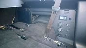
PS2 + Split charge system 10 viewsPS2 - Wireless controllers and headphones.
Split charge system with auxiliary sockets with digital voltage display
|
|

Mechatronic Replacement Hints plus drains for steel and plastic pans1111 viewsThis 22 page pdf shows colour views of the Mechatronic unit as well as good illustrations of the drain and fill ports in both the plastic, page 17, and steel pans, page 18.
Page 8 details the replacement of the sealing sleeve where the electric wire feed thru the case into the Mechatronic unit. The seal is normally replaced when a new pan is installed as the seal is a known leakage point.
|
|
|
|
|