| Search results - "Relay" |

remove relay 7 - pair of plyers is proberly easiest 867 views
|
|

find relay 7 in engine compartment fuse / relay box 806 views
|
|

TB 149584 - Air Suspension Compressor and Relay Replacement41 views
|
|
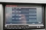
17298 viewsYou can add relay switches to the controller to turn on & off from the touch screen...pretty cool.
|
|
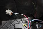
109 viewsThis is the plug for the accessory socket at the rear of the cubby box. On commercial D3 such as this one, there is no accessory socket so this plug is unused. I tapped into the 12V wire as an ignition feed. This will feed a relay coil which opens up power from the aux battery. Like this I can still retro fit and make use of the accessory socket later on.
|
|
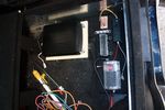
97 viewsDeciding on a layout for the electrical stuff. Bottom right of pic is a fusebox which will take the input power from the traxide kit, then relay box and 12V regulator, ignition busbar and homemade regulated 12V busbar. Big black box is the CarPC
|
|
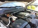
Traxide USI-160 Install517 viewsOverview picture of Traxide USI-160 upgrade install. This was an upgrade from the SC80 which performed flawlessly. The USI-160 had two relays and can deliver more amperage. As a result, the wiring was upgraded to 4/0 Welding Cable (warn) and heat shielding was added. The unit performs flawlessly to support 2 HAM Radios, Fridge, etc. Like me https://www.facebook.com/DifferentialPartsUS
|
|

53 views
|
|
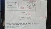
Thread upload10 viewsImage uploaded in thread 192103
|
|

Genlabs 230 views
|
|
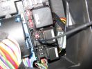
aux sockets relay - remove the relay and put in link wire 192 views
|
|
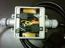
Box open showing Hella Relays and Putco Load Resistors750 viewsInterior of the box - note the two gold coloured 6 ohm 50 watt load resistors are a bit distant from the other items so as to provide some separation for dissipation of the heat generated.
Rather than a moulded plastic weather resistant box which I would have preferred, I used a bulky and much heavier metal weather tight style electrical box so the metal can act as a heat sink.
|
|

Thread upload0 viewsImage uploaded in thread 103185
|
|

Thread upload3 viewsImage uploaded in thread 103185
|
|
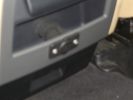
Auxiliary power sockets - TracTronics, Australia383 viewsA complete kit including two outlets, wiring etc connected to auxiliary Optima Blue top battery using their very effective SC40 split charge relay. One outlet between rear and front seats, and 2nd alongside loadspace 12v outlet, enables fridge to run when engine is not running, without affecting start capacity or vehicle functions.
|
|
D3_Glow_Plug_Relays20 views
|
|

Thread upload23 viewsImage uploaded in thread 176837
|
|
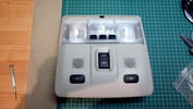
Roof console with mounted switches150 viewsOne switch is for switching the R-750 spot lamps, the other is for additional external lighting using a second Relay kit provided by OEM Plus.
|
|
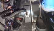
Electronic Relay159 viewsRelay mounted to mounting frame of the brake pedal
|
|

you can see the fuse on the L and the relay on the R174 views
|
|
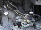
DLR relay install71 views
|
|
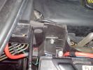
aux battery 120amp relay213 views
|
|

Wiring Diagram Fog Lamps76 viewsR130 is the (R5 relay under the hood) The wire is blue grey that is hot when the high beams are on and opens the relay contact that turns off power to the fog lamps. North America Only
|
|
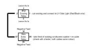
Retro fitted Headlamp Washer Relay Rewiring Circuit Diagram301 views
|
|

Underside of the ciruit board129 viewsThis looks more of a mess than needed to be. The Maplins guy tried to be helpful when I bought the relays, he wrote down the switching COM/NO/NC, it was actually NC/COM/NO. Some scratching of head when it didn't work then worked out what happened when I looked on the manufacturers website at the data sheet...lesson of the day check the data sheet!
|
|

Relay kit12 views
|
|

Relay kit 219 views
|
|
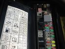
Compressor Relay30 views
|
|

Relay kit 314 views
|
|

Aux Battery918 viewsShopwing the addition of the 35mm2 cable going to the split charge relay
|
|
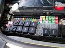
Picture of the engine compartment fuse panel5789 viewsEngine compartment fuse panel located near the battery. This is where F3E, (5 amp), F26E, (20 amp), Fuseable link 10E, (60 amp) and Relay 7E, the now upgraded 70 amp air compressor motor relay, part number YWB500220, (E is for Engine compartment fuse box), are all located. Fuse F35P, (5 amp), is inside the Passenger compartment behind the lower glove box door.
To keep the suspension from going down to the stops when driving, (or parked), it appears that it is only really necessary to remove F26E to depower the exhaust valve and generally keep all the valve block solenoid valves in a closed position trapping whatever air is within the air springs. F3E gets its power thru F26E, so when F26E is removed, the F3E circuit is automatically de-powered. F35P is more interesting in that battery power goes thru the ignition switch and F35P and then into the air suspension control unit. Apparently however, if F26E is removed, removing the F35P is not needed even when the engine is running.
With all fuses still in, if you have a problem, in practice, ideally, the compressor still works and will raise the 3 to an appropriate height. If so, one can then shut the engine off and allow the computers to go to sleep and then you remove the fuse(s). In actual practice, it seems that one need only pull the F26E fuse and can do so with the engine running. All the same, one might consider that the 3 is first a mobile computer, and secondly a 4x4. Computers prefer to go to sleep before the plug is pulled on them, however given that F26E circuit is always alive, then the computer never sleeps. With the fuse(s) pulled, and if you are still up, you can now be a 4x4 instead of a low rider. The whole purpose of the fuse pulling exercise is to depower the one and only system exhaust valve that is physically located within the compressor unit, (to keep it from opening), and secondarily to keep closed the four air spring solenoids within the block valves. This also shuts the air compressor down and stops the air compressor from making air even if the compressor is still good. That is why you initially need the fuse(s) in to allow the compressor to make air if it can.
|
|

Thread upload1 viewsImage uploaded in thread 103185
|
|

Thread upload3 viewsImage uploaded in thread 103185
|
|

Air Suspension System Parts, Layout, and Operation7073 viewsThis 22 page pdf gives a pretty good description of how the system is supposed to work, plus shows the various parts and the electrical including fuses and relays etc. Of the files here, this is the most useful.
As with all the pdf's here, you can download and print it out.
|
|
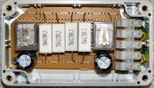
All the components assembled ready for wiring.831 viewsThe 5watt resistors get fairly hot, be careful not to have them touching the relay case or use a larger box for yours.
|
|
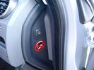
Air Suspension ECU Fuse 35P cut off switch.3826 viewsThis shows the SPST rocker switch mounted in the blank plate installed in lieu of a manual passenger side air bag shut down switch - now automatic via passenger seat pressure switch. Fuse 35P (5 amps) is located in the interior fuse box behind the lower glove box and protects the ignition power supply to the Air Suspension ECU. When the SPST switch is moved to the OFF position, the RAISE /LOWER switch on the centre console is not powered, and hence does not function. As such, some signals from the wheel height sensors and CPU are ignored. By itself however, removing F35P will probably not stop the 3 from self dropping, particularly after the engine is turned off.
Fuse F3E, (5 amps), located in the engine bay fuse box by the starting battery protects the circuit that provides feedback to the Air System ECU indicating that the Compressor Relay has successfully operated and that the Air Compressor is or should be operational, can also be removed, (but is probably not totally necessary), as it gets its power thru F26E. Hence Fuse F26E, (20 amp), also located in the engine compartment fuse box is the fuse that must be removed. This fuse protects the circuit that provides full time battery power to the Air System ECU. When in place, current thru the fuse powers the periodic re-levelling action, (usually lowering a bit with that brief air release noise), that often occurs when the vehicle is parked and the engine is off.
Removing F26E fuse will stop the auto levelling action and also inhibit any other down to the stops signals, (engine running or not). When F26E is removed, no power can flow thru to F3E, hence removing F3E is more for insurance than an absolute requirement. The same with F35P, removing F26E removes primary full time power from the Air Suspension ECU, and hence removing the F35P fuse should not really be required either as long as F26E has been removed.
|
|
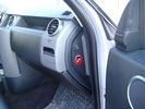
Air Suspension ECU Fuse 35P Shut Off Switch2639 viewsA more distant view of the shut off rocker switch in the ON position which is the normal position for when all is working as Land Rover intended.
Ideally, (but not totally necessary), the F35P circuit should be powered or de-energized after the various computers have gone to "sleep".
Similarly, removal of the F26E or F3E fuses is preferable after the computers have all gone to sleep but it appears that no real damage will be done if the fuses are removed while the system is energized. Pulling F26E is the main full time fuse that powers the air suspension computer. As such, once F26E is removed, pulling F3E is not really required.
Power for the compressor goes thru the 60 amp fusible link and relay, however control of the relay is via the air suspension computer so depowering the air suspension computer effectively depowers the air compressor and the internal exhaust valve relay/port.
|
|
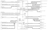
Power Window Circuit centered on Central Junction Box (behind glove box fuse panel)738 viewsRelay 143, the power window relay, and most other relays and FET's as well are built into the back of the passenger side behind the lower glove box fuse panel.
As such, the relays etc are not removable, jump-able, or serviceable.
|
|
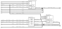
Power Window Circuit Sheet 2 Central Junction Box to Passenger Front Switch366 views
|
|

LR3 Electrochromatic Interior Rear View Mirror wiring diagram.856 viewsIt seems that there are two fuses, F69P and F5P that provide power for the interior rear view mirror. Ten amp F5P is a feed off the reverse gear relay and inhibits auto dimming when reverse is selected. Five amp F69P provides power to the auto dimming circuits and the garage door opener function if optioned.
The pdf can be downloaded and printed out. For on screen viewing, right click on the pdf and select the Rotate Clockwise button.
|
|

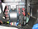
Underhood Fuse and Relay Box drawing 3059 viewsShows the various fuse and relay locations. Fuse 3E, (5 amp), and Fuse 26E, (20 amp), as well as upgraded 70 amp Relay 7, part number YWB500220, locations are displayed. Relay 7 sends battery power to the compressor from the 60 amp fusible link called up as 10E. Fuse 26E is what provides full time always on battery power to the air suspension ECU and hence powers the auto level wakeup when the vehicle is shut down and say parked for the night. Removing F26E is the primary method to disable the air suspension system; Removing F35P is more if you want to experiment with it from inside.
I found it useful when I had a suspension problem, (actually a wheel alignment problem picked up by the steering wheel angle sensor), that only showed itself on the highway but allowed for no trouble light driving in the city. This was because in the city, the steering wheel was always in motion and rarely was the vehicle driven in a near straight line for very much distance.
|
|
Thread upload43 viewsImage uploaded in thread 47507
|
|

Horn Wiring Circuit LR3580 viewsThe is the wiring diagram for the dual horn circuit.
The Horn Relay, (R133), is not a big black thing hidden somewhere but instead what is called a FET, (and it is hidden)!
This is a Field Effect Transistor that is built into the circuit board that is mounted to the back of the fuse box that is located behind the lower glove box door on the passenger side of the 3. The related 15 amp fuse, 12P, is mounted in this fuse box and is often called F12P, where F is for fuse, and P is for Passenger compartment.
This is to help differentiate from another fuse and relay box, (the usual kind), that is located beside the starting battery in the Engine compartment. FxxE is often used in the naming of those fuses.
|
|

Stop Light Lamp Circuit pdf2496 viewsThis pdf shows the brake light circuit for the NAS LR3.
Note that power for the brake light bulbs can come either thru the brake light switch power feed /contacts plus also from the Hill Decent Control, (HDC), system relay located within the Central Junction Box, (CJB) - yes two separate sources of power for the brake light bulbs. This would tend to explain how a brake light circuit concern shows up as a hill decent fault message; also why lesser vehicles without hill decent braking mechanisms, (HDC), never display this sort problem when a brake light bulb or switch acts up. You never have a problem related to a system that does not exist.
Additional evidence of the relationship of the HDC and the tail light circuit is demonstrated by when the HDC actually acts to slow the 3 down, the brake lights automatically illuminate even if the slowing action was merely retarding the engine speed or shifting to a lower gear, (in other words, no foot on the brake pedal).
There is also a tie in to the Cruise Control and hence a failing brake light switch can affect cruise operation or just create false Cruise Control messages. To further complicate the issue, while there are no messages generated, operation of the radiator electro viscous fan can also be negatively affected by the fouled set of secondary contacts within the brake light switch. This is all because the NC contacts within the brake switch send misleading messages to the ECU.
While the ground wire design is similar to other vehicles, note the grounds for the brake light filament and the reverse light filament are common on each side. That means that if one has a non functioning brake light on one side, the reverse light may not also work or that some problem with the reverse lights could back feed into the brake lights. This situation while unusual, can result when grounds are corroded probably due to swimming in rivers and creeks or just routine driving in a marine environment.
|
|

Heated Windscreen Wiring Diagram410 viewsThis single page pdf is the heated windscreen wiring diagram. You can rotate the view by right clicking on the pdf and of course it can be printed out as well.
Relay R208 in the pdf is relay R9 in the Engine Compartment fuse box. Note both 30 amps fuses, F15E and F18E, also located in the Engine Compartment fuse box. If one side of your windscreen does not heat, the problem may be one of the two fuses.
|
|

LTB00331 - Technical Bulletin - Air Suspension Compressor and Relay Replacement224 views
|
|

Thread upload6 viewsImage uploaded in thread 175327
|
|
48 views
|
|
Relay Change246 viewsYWB500220 electrical, fuse & relay, relay ENGINE COMPARTMENT, 70 amp 1
|
|
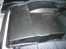
Relay Change220 views
|
|
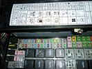
Relay Change379 viewsYWB500220 electrical, fuse & relay, relay ENGINE COMPARTMENT, 70 amp 1
|
|
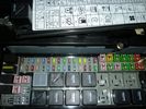
Relay Change285 views
|
|
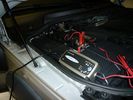
Relay Change266 views
|
|
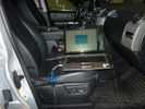
Relay Change305 views
|
|
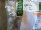
LR020590 KIT - COMPRESSOR 1481 viewsThere are 4 main parts you can get besides a whole compressor. This is the one with only a spring, o-ring and rubber valve.
YWB500220 electrical, fuse & relay, relay ENGINE COMPARTMENT, 70 amp 1
LR020590 KIT - COMPRESSOR 1
JPO500010 KIT - COMPRESSOR 1
VUB504700 - Dehydrator PARTS
|
|
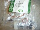
JPO500010 KIT - COMPRESSOR 1437 viewsThere are 4 main parts you can get besides a whole compressor. This is the one with more bits.
YWB500220 electrical, fuse & relay, relay ENGINE COMPARTMENT, 70 amp 1
LR020590 KIT - COMPRESSOR 1
JPO500010 KIT - COMPRESSOR 1
VUB504700 - Dehydrator PARTS
|
|
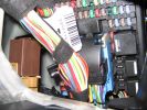
powerfold relay275 views
|
|
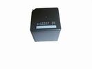
Front Blower R16 relay, part number YWB500060485 viewsThis is the front fan relay located in the engine compartment fuse box. It should be replaced and installed new when a new fan is installed.
|
|
68 views
|
|
67 views
|
|

12 views
|
|

Thread upload15 viewsImage uploaded in thread 127724
|
|
Thread upload5 viewsImage uploaded in new thread
|
|
78 views
|
|
83 views
|
|

11 views
|
|
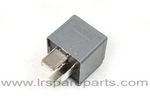
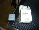
Air Compressor 70 amp replacement relay1396 viewsThere is a software update, 09 April 2010, LTB00270, for the compressor which reduces the shut down pressure to about 205 psig (14 bar). The update is usually done when changing to a new compressor and also includes replacing the R7 relay in the engine compartment fuse box, 07 DEC 2010 LTB00331.
The newer grey case coloured relay, part # YWB500220, shows to be rated at 70 amps, (the relay, not the compressor), however the previous black case coloured relay also indicates 70 amps.
Both the new and replaced relay show on their wiring diagrams to have a parallel voltage spike resistor, (probably 560 ohms), across the coil terminals, #1 and #2. This means one does not just replace the relay with any four prong 70 amp ISO sized relay that one happens upon.
One presumes the grey relay is either upgraded or just being installed for good measure. The relay is common on Ford Fiesta for the seat heater relay, Ford part number 5M5T 14B 192 EA; also Volvo, part number 30765034. The Tyco part number moulded on the grey body is V23136-J4-X62.
|
|

Thread upload15 viewsImage uploaded in thread 127724
|
|
Thread upload30 viewsImage uploaded in thread 99488
|
|

81 views
|
|
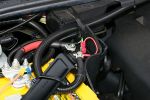
IBS split charge relay102 views
|
|
![Filename=Technical Service Bulletin SB034 SB036 Vehicle Enhancement Program[1].pdf
Filesize=959KB
Dimensions=0x0
Date added=17.Jun 2010 Technical Service Bulletin SB034 SB036 Vehicle Enhancement Program[1].pdf](images/thumb_pdf.jpg)
Technical Service Bulletin SB034 SB036 Vehicle Enhancement Program2391 viewsOn page 6 and following are the Land Rover service bulletin instructions as to how to install delivery valve and exhaust valve repair kit JPO500010; also a list of previous compressor model numbers as related to the 3. The new delivery valve is easy to install, the exhaust, not so easy. Note that this in not the more recent TSB that reduced the operating pressure of the compressor via a software fix and also recommended replacement of the air compressor 70 amp relay. See the F35 album near the bottom for the relay material.
|
|
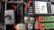
Thread upload10 viewsImage uploaded in thread 106191
|
|
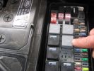
windscreen relay217 views
|
|
|
|
|
|